Structure light 3D measuring technology based on edge gray code and line movement
A measurement method, Gray code technology, applied in the direction of measurement devices, photogrammetry/video measurement, surveying and navigation, etc., can solve the problem of spatial point measurement accuracy, sampling density without substantial improvement, and projection angle space division. Continuous and other problems, to achieve the effect of improving adaptability, strong adaptability, and eliminating one-bit decoding error
- Summary
- Abstract
- Description
- Claims
- Application Information
AI Technical Summary
Problems solved by technology
Method used
Image
Examples
Embodiment 1
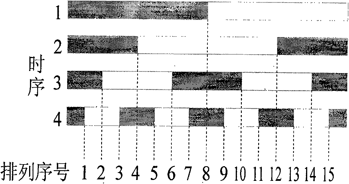
[0029] The existing time coding methods all divide the projection angles based on binary codes and Gray codes, or further subdivide the projection angles by combining phase shift method or vertical layering method on this basis. The above methods use pixels as image sampling points, which is called pixel-centered decoding.
[0030] There may be several bits of difference between the adjacent code values of the binary code, which is reflected in the decoding process, that is, some pixels may be on the edge of the stripes many times in each intensity image, so their code values may be misjudged by multiple bits. If the judgment exists in the high position, the decoding error will be larger. There is only one bit difference between any two adjacent code values of the Gray code and the weights of each bit are the same, which is reflected in the decoding process, that is, any pixel is at the edge of the stripe at most once in each intensity image, so only one bit of its code ...
Embodiment 2
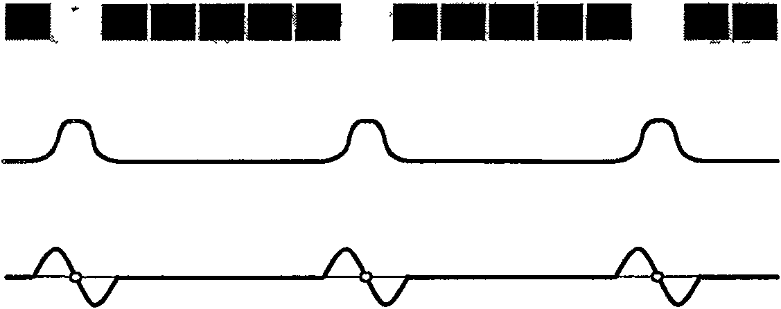
[0038]Gray code edge decoding eliminates a conversion error, but reduces the image sampling point density to a certain extent. Theoretically, when the width of the thinnest stripe in the intensity image is 1 pixel, the gray code edge decoding can obtain the same image sampling point density as the pixel center decoding. On the basis of code edge decoding, the sampling density of image points is doubled, and at the same time, the sub-pixel accuracy positioning of image sampling points is guaranteed.
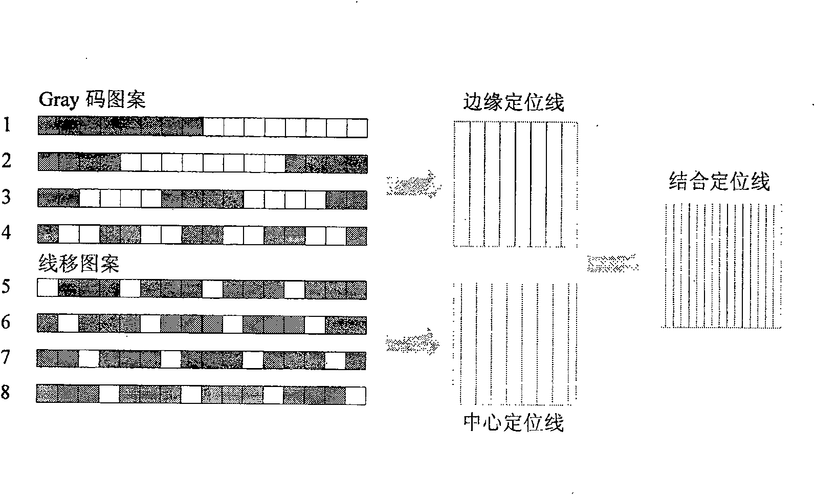
[0039] Such as figure 2 As shown in the left figure, four periodic line-shifting stripe patterns are projected sequentially after the Gray code pattern is projected. The line shift period is equal to the Gray code period width. Each line shift cycle contains 1 white stripe and 3 black stripes. The width of the white stripes is equal to the width of the thinnest stripes in the Gray code pattern, and the direction is parallel to the Gray code stripes. Two adjacent patterns are ...
Embodiment 3
[0045] Using multiple anti-color dynamic thresholding method. First, binarize the coded image, which requires projecting a full-brightness pattern and a full-darkness pattern, then the grayscale of each point of the first coded image (the high-bit coded image after binarization) is equal to the first coded image The difference between the gray level of the (high-bit coded image before binarization) and the full dark image is divided by the difference between the full bright image gray level and the full dark gray level, and its value is between 0 and 1. Then project the inverse reference pattern 1 corresponding to the first coded image (high-order coded image before binarization), then the grayscale of each point in the second coded image (high-order coded image after binarization) is equal to the second The absolute value of the difference between the gray level of the coded image (the high-order coded image before binarization) and the first coded image (the high-order coded...
PUM
 Abstract
Description
Claims
Application Information
 - R&D
- Intellectual Property
- Life Sciences
- Materials
- Tech Scout
- Unparalleled Data Quality
- Higher Quality Content
- 60% Fewer Hallucinations
Browse by: Latest US Patents, China's latest patents, Technical Efficacy Thesaurus, Application Domain, Technology Topic, Popular Technical Reports.
© 2025 PatSnap. All rights reserved.Legal|Privacy policy|Modern Slavery Act Transparency Statement|Sitemap|About US| Contact US: help@patsnap.com


