

Inter-frequency cell updating test method
A cell update and testing method technology, applied in electrical components, selection devices, wireless communication, etc., can solve the problems of inability to perform complete testing and no RACH/FACH channel.
- Summary
- Abstract
- Description
- Claims
- Application Information
AI Technical Summary
Problems solved by technology
Method used
Image

Examples
Embodiment Construction
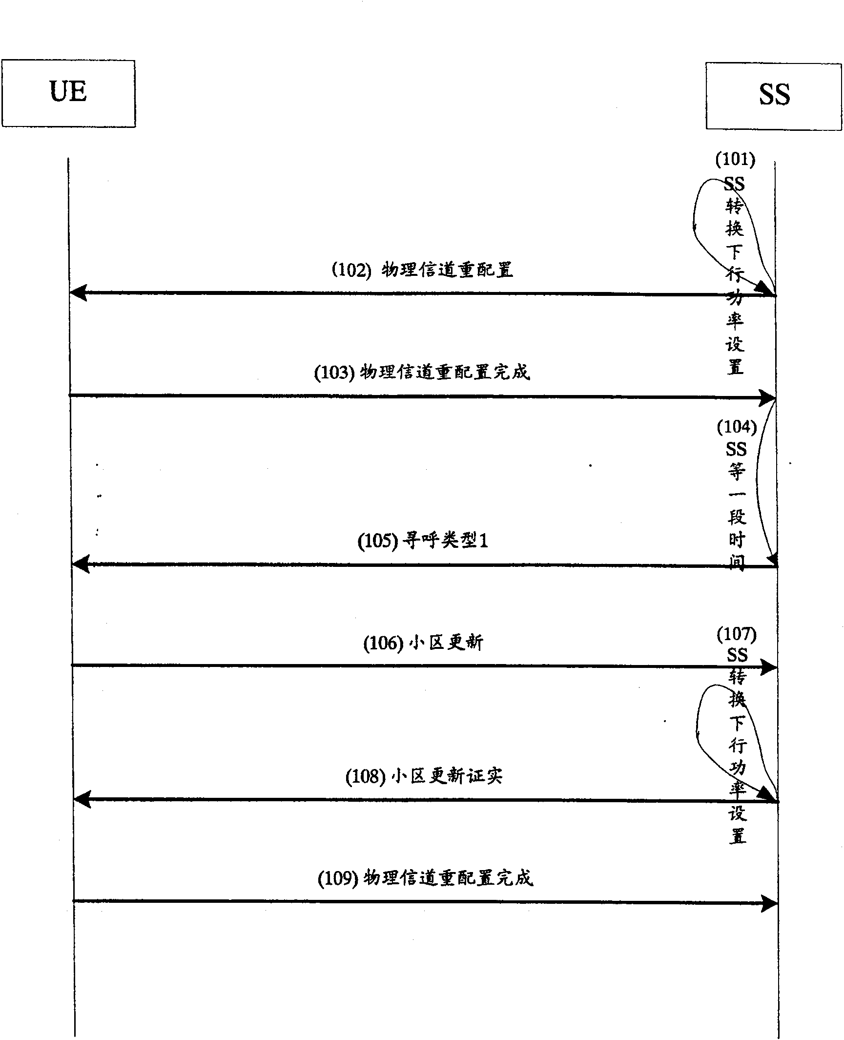
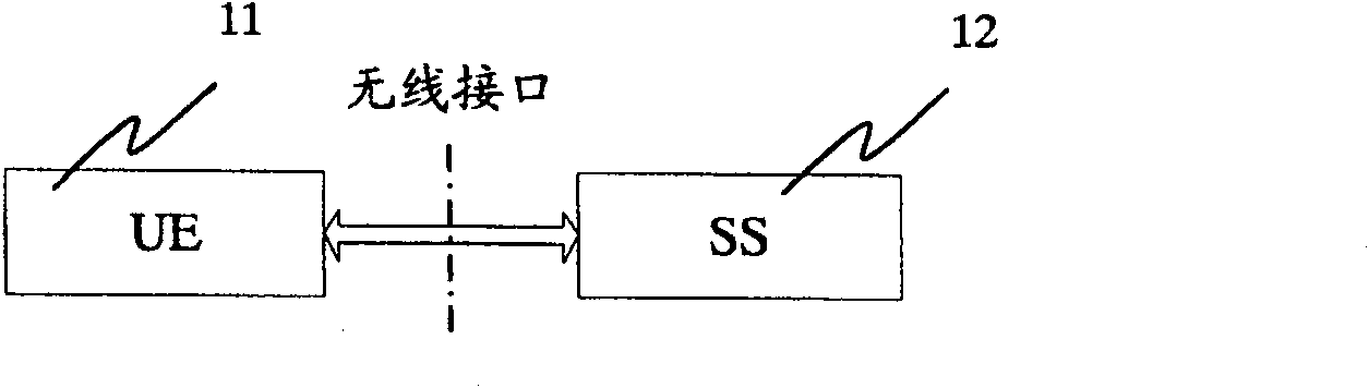
[0049] The device diagram of an embodiment of the present invention can refer to figure 2 . Such as figure 2 , the device of an embodiment of the present invention includes a system simulator SS 12 and a user equipment UE 11 supporting E-DCH channels, and the SS 12 is connected to the UE 11 through a wireless interface to perform a cell update test. The initial test condition is set as follows: the system simulator SS 12 simulates two cells 1 and 6 (generally referred to as two cells, or cell A and cell B), wherein cell 1 is activated, and cell 6 is inactive; UE 11 is in cell 1, and the state is PS-DCCH+DTCH_HS-DSCH+DTCH_E-DCH (state 6-18) under the condition of A14 (state definition refers to document TS34.108).
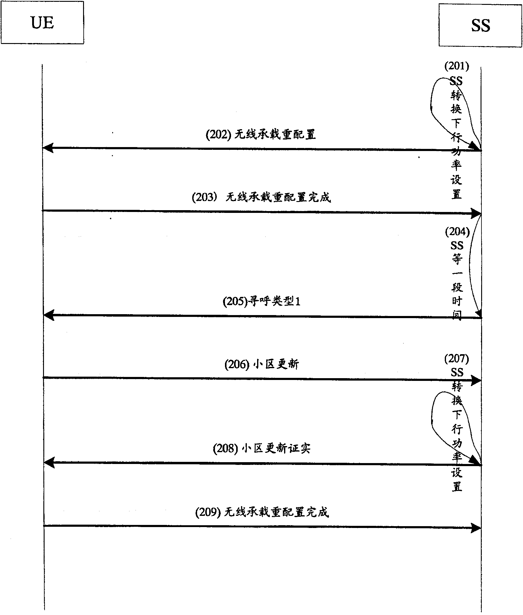
[0050] The test flowchart of an embodiment of the present invention can refer to image 3 . Such as image 3 , the testing method of the present invention comprises the following steps:
[0051] Step 201: The SS switches the downlink power setting, and chang...
PUM
 Abstract
Description
Claims
Application Information