A high-reliability multi-channel na-level micro-current transmission design method

A design method and micro-current technology, applied in the direction of measuring current/voltage, measuring electrical variables, measuring resistance/reactance/impedance, etc., can solve the problem of low indicators, waste of time, and restriction of electronic components in the detection and screening of automatic test systems for capacitor insulation resistance. The development of device screening and detection has achieved the effect of solving the problem of inspection and ensuring normal transmission.

Inactive Publication Date: 2016-08-17
THE 41ST INST OF CHINA ELECTRONICS TECH GRP
View PDF5 Cites 0 Cited by
  • Summary
  • Abstract
  • Description
  • Claims
  • Application Information

AI Technical Summary

Problems solved by technology

[0006] The existing automatic test system for capacitor insulation resistance detection and screening has low indicators, and can only screen for civilian-grade capacitors, which completely fails to meet the screening standards for aerospace-grade or even military-grade capacitors. Development of device screening and detection, and screening inefficiencies
[0007] 2. The single-channel micro-current detection index can meet the requirements, but it cannot form multi-channel micro-current detection for automatic testing
[0008] The existing technical basis is that capacitor manufacturers and trial manufacturers basically use manual detection of insulation resistance of capacitors. There is no automatic testing and screening system, and only a large number of components can be tested one by one, which wastes time and is manually tested. The introduction of test errors restricts this test is the technical bottleneck of micro-current detection

Method used


Image

  • A high-reliability multi-channel na-level micro-current transmission design method
  • A high-reliability multi-channel na-level micro-current transmission design method

Examples


Embodiment Construction

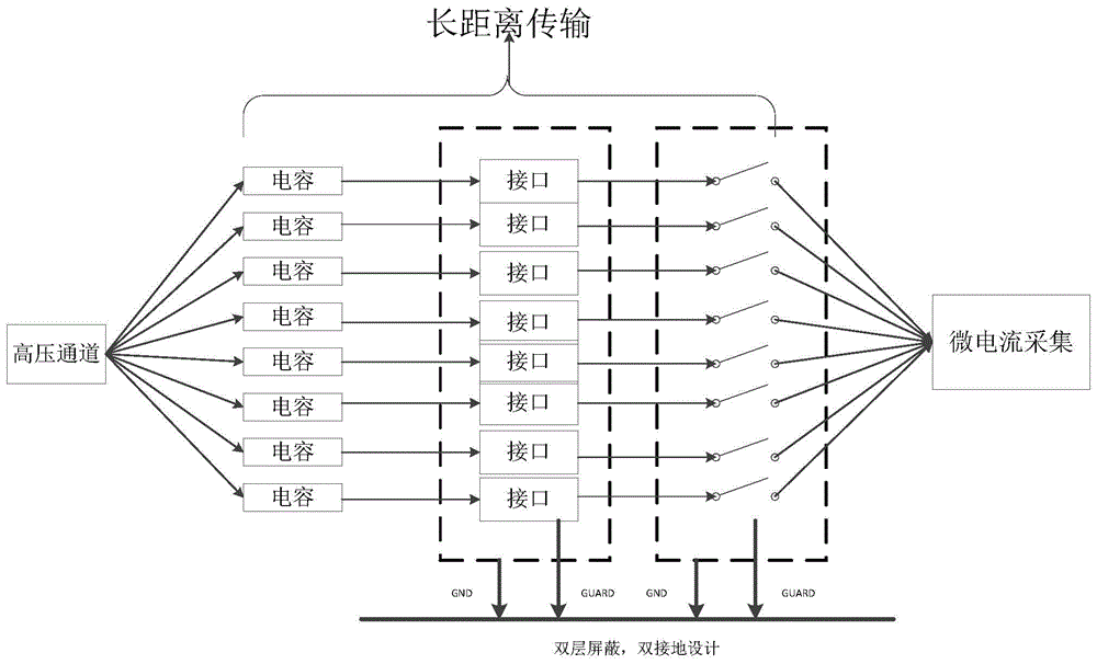
[0033] combine figure 1 , a multi-channel nA level micro-current transmission design method, comprising the steps of:

[0034] a Shielding protection and seamless connection design steps to ensure that micro-current signals are not disturbed by the outside world; specifically include:

[0035] a1 The entire micro-current circuit is fully shielded;

[0036] a2 Select double-shielded cables as connecting cables to achieve multi-layer protection and minimize external interference of micro-currents;

[0037] a3 Choose double-shielded connectors, which are consistent with the above-mentioned double-shielded cables, so that the micro-current transmission process can be seamlessly connected to ensure that the circuit is not disturbed by the leakage current of the material insulation;

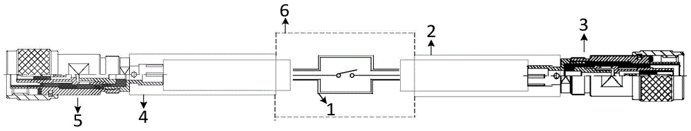
[0038] a4 Select a wiring relay, the connector of the wiring relay is an SMA connector to ensure that the entire micro-current transmission process is a floating design, and the outer layer of the en...


PUM


Abstract

The invention discloses a multi-channel nA-level micro-current transmission design method, which is characterized in that it includes the following steps: shielding protection and seamless connection design steps to ensure that the micro-current signal is not interfered by the outside, and the step includes the entire micro-current loop for complete Shielding, selecting double-shielded cables as connecting cables, selecting double-shielded connectors and selecting wired relays; PCB board design steps to ensure the independence of loop signals and not be affected by switching signals. This step includes placing the entire circuit on the printed board. The micro-current test path is suspended to ensure the isolation of leakage current interference; c is a layered design step to separate the high-voltage circuit from the micro-current detection circuit. The invention not only ensures the normal transmission of micro-current, but also successfully solves the problem of testing the insulation resistance of 1TΩ aerospace-grade capacitors at the highest voltage of 1000Vdc, and can be widely used in testing the insulation resistance of civilian-grade, military-grade, and aerospace-grade capacitors. Measurement.

Description

technical field [0001] The invention relates to a multi-channel nA level micro-current transmission design method. Background technique [0002] There are a large number of DC weak current signals in scientific research, teaching experiments, and production practice. With the continuous development of modern electronic technology and measurement technology, the measurement of weak current has become more and more important. Microcurrent measurement is easily affected by the noise generated by the surrounding environment and the circuit itself. In the traditional concept, in order to reduce the interference of the weak current circuit, it is advisable to use a signal line with a shielding layer, and the shielding layer should be grounded at both ends, and the microcurrent Long-distance, multi-channel transmission also poses new problems for today's designs. [0003] The existing test technology is that the insulation of the PCB board can reach the index that the micro curre...

Claims


Application Information

Patent Timeline
Patent Type & Authority Patents(China)
IPC IPC(8): G01R19/00G01R27/02
Inventor 乔宏志薛沛祥秦赞
Owner THE 41ST INST OF CHINA ELECTRONICS TECH GRP
Why Eureka
Try Eureka