

Pile bottom post-grouting method
A post-grouting and pile-bottom technology, which is applied to sheet pile walls, buildings, and foundation structure engineering, can solve problems such as unsatisfactory construction effects, and achieve the effects of improving grouting effects, increasing strength, and increasing stiffness
- Summary
- Abstract
- Description
- Claims
- Application Information
AI Technical Summary
Problems solved by technology
Method used
Image

Examples
Embodiment Construction
[0015] A post-grouting method at the bottom of a pile, comprising the following steps:
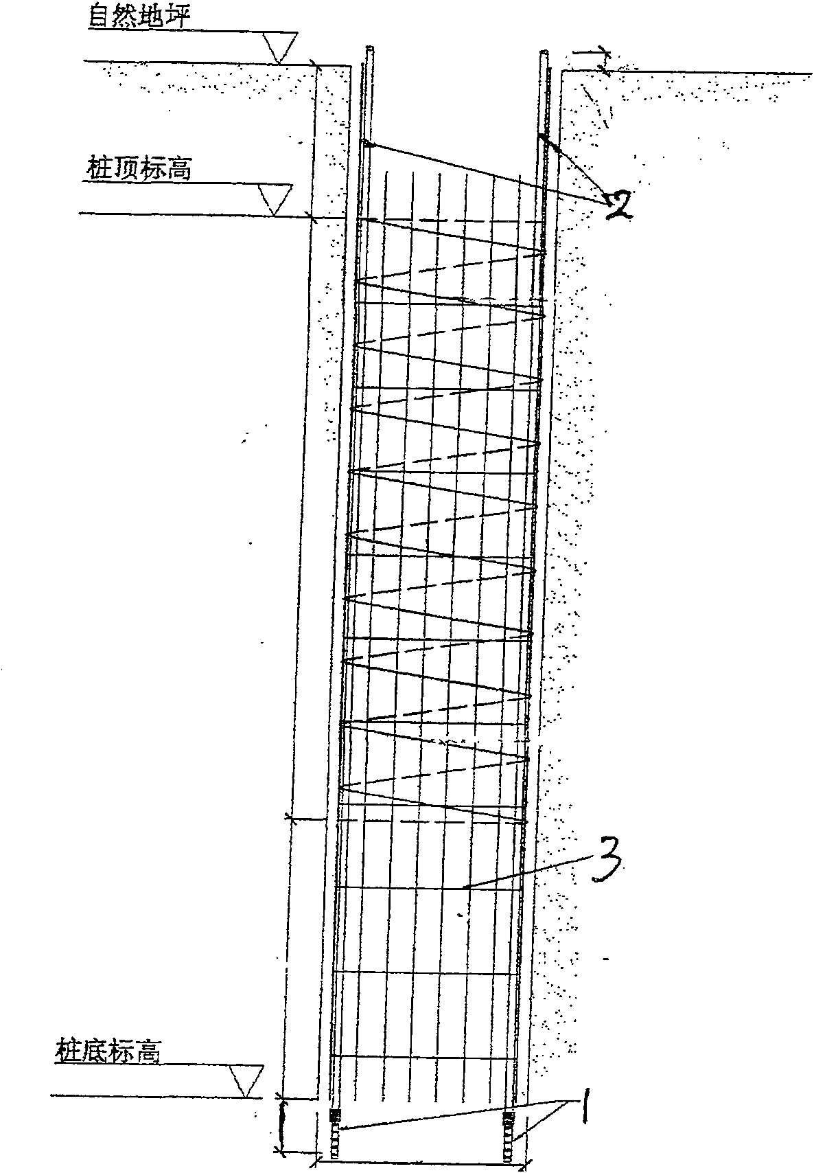
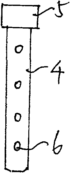
[0016] (1) During the construction of the bored pile, the grouting pipeline is preset at the bottom of the pile: the grouting device 1 is fixedly connected with the grouting pipe 2, and the grouting pipe 2 is placed in the steel cage 3, and the iron wire is connected with the grouting pipe 2. The reinforcement cages are tied together and lowered together with the reinforcement cages. The grouting device extends 0.4 to 0.8 cm from the bottom of the reinforcement cage, and the grouting device is inserted into the pile bottom sediment and void soil to ensure the smooth flow of the grouting pipeline; The grouter includes a grouter pipe 4 (using steel pipe or high-strength PVC pipe, etc.), the feed end of the grouter pipe is equipped with a one-way valve 5 connected to the grouting pipeline, and the outer circumference of the grouter pipe wall is provided with multiple Pulp hole 6;
[0017] (2...
PUM
 Abstract
Description
Claims
Application Information