
Liquid division type double-pipe condenser

A condenser and casing technology, which is applied in the field of liquid-separated casing condensers, can solve the problems of reduced heat transfer coefficient, degraded condensation effect, and poor condensation effect, so as to reduce thickness, reduce production and operation costs , the effect of improving performance

Inactive Publication Date: 2010-01-20
TSINGHUA UNIV
View PDF5 Cites 0 Cited by
  • Summary
  • Abstract
  • Description
  • Claims
  • Application Information

AI Technical Summary

Problems solved by technology

During the condensation process, the liquid film gradually thickens, and in the long-term later, it will be a complex two-phase flow in which the liquid gradually increases, the thermal resistance will gradually increase, and the condensation effect will deteriorate seriously; at the same time, with the condensation of the steam, the amount of steam will gradually decrease. The steam flow rate in the tube drops significantly, the condensation effect degrades sharply, and the heat transfer coefficient decreases; the condensation process in a single tube process also leads to complex gas-liquid two-phase flow, which has great impact on system operation stability, flow resistance and system regulation. negative effect

Method used


Image

  • Liquid division type double-pipe condenser
  • Liquid division type double-pipe condenser
  • Liquid division type double-pipe condenser

Examples


Embodiment Construction

[0025] Further illustrate the present invention below in conjunction with accompanying drawing.

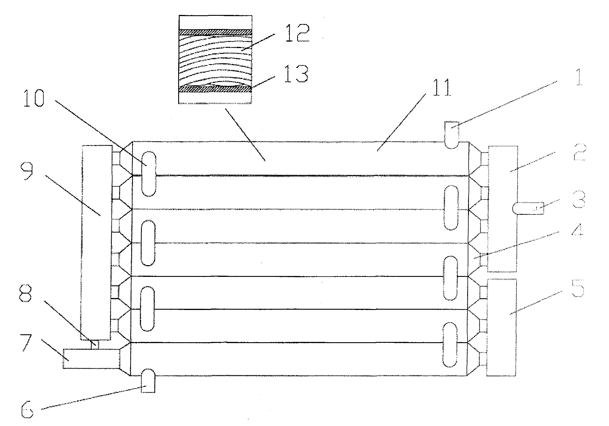
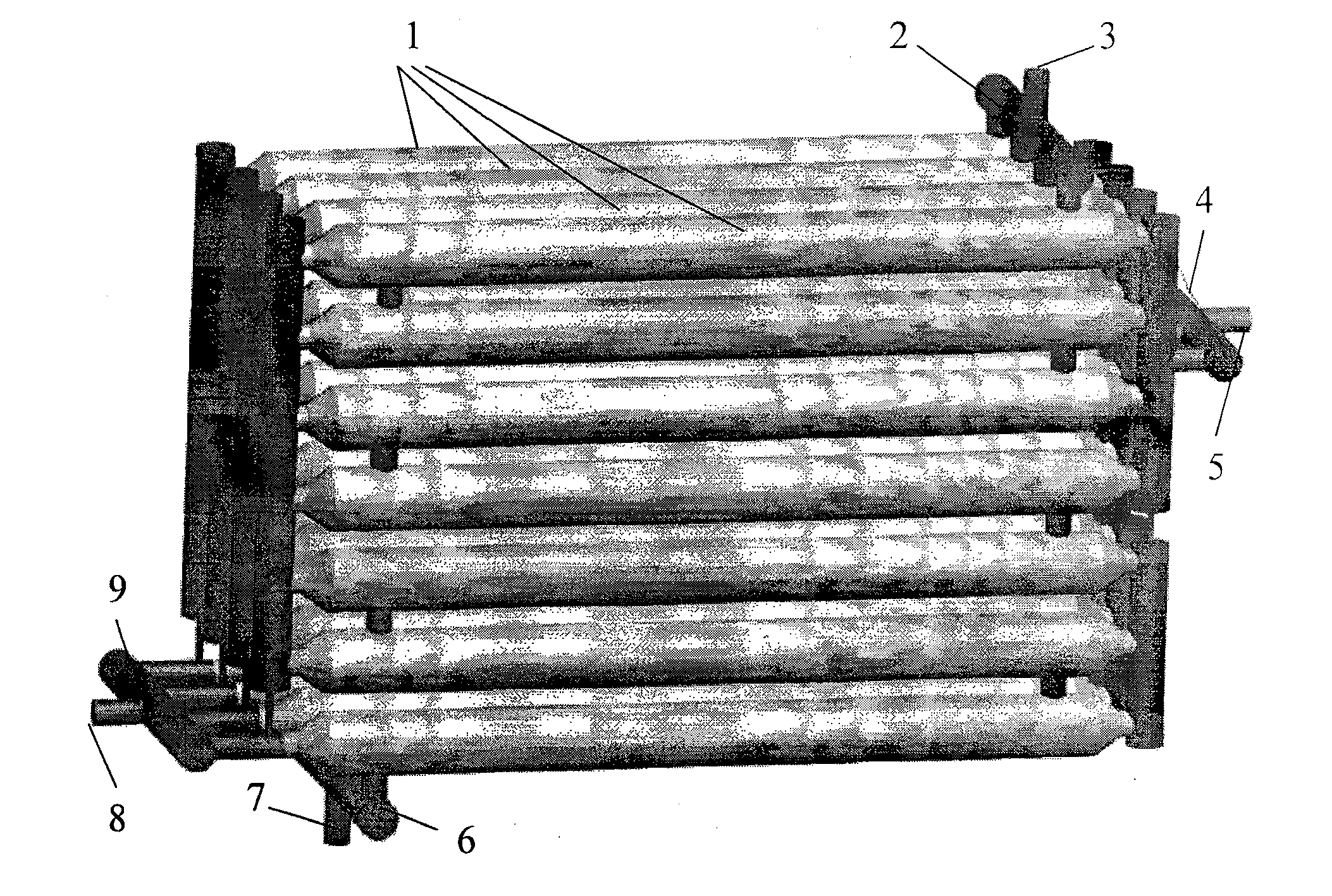
[0026] figure 2 It is a schematic diagram of a single-flow split-pipe condenser of the present invention. Among them, 1. Cooling water inlet, 2. The first cascade box, 3. Condenser steam inlet, 4. Steam collector, 5. The last cascade box, 6. Cooling water outlet, 7. Condensate outlet, 8. Liquid discharge pipe, 9. Second cascade box, 10. Outer casing catheter, 11. Heat exchange casing, 12. Inner tube, 13. Outer casing. Each heat exchange sleeve (11) is composed of an outer sleeve (13) and several inner tubes (12). The two ends of the inner tube are connected with steam collectors (4), and the steam collectors (4) are connected to the cascades at both ends. tank or the condensed steam / liquid inlet and outlet; The steam collectors (4) at both ends of each tube are connected to the second cascade box (9); the second cascade box (9) passes through another set of heat exchange sleev...


PUM


Abstract

The invention relates to a liquid distribution type casing pipe condenser, which belongs to the heat equipment technology field, and comprises a cooling water inlet (1), a first stage header (2), a condenser steam inlet (3), a last stage header (5), a cooling water outlet (6) and an internal pipe (12), wherein the two ends of the internal pipe (12) are connected with a water (steam) collecting head (4), the condenser steam inlet (3) is connected with the first stage header (2) and connected with a second stage header (9) through a first group heat exchange casing pipe (11) and the water (steam) collecting head (4) of the two ends of the first group heat exchange casing pipe, the second stage header (9) is communicated with a next stage header through the other group heat exchange casing pipe (11) and the water (steam) collecting head (4) of the two ends of the other group heat exchange casing pipe; ellipsis; until the last stage header (5). The invention effectively reduces the liquid film thickness and the adverse two-phase flow pattern in the condensation process, increases the heat exchange effect of film condensation, improves the condensation heat exchange coefficients in the pipe and the performance, saves materials, simplifies processing, and reduces the manufacturing and operating cost of the condenser.

Description

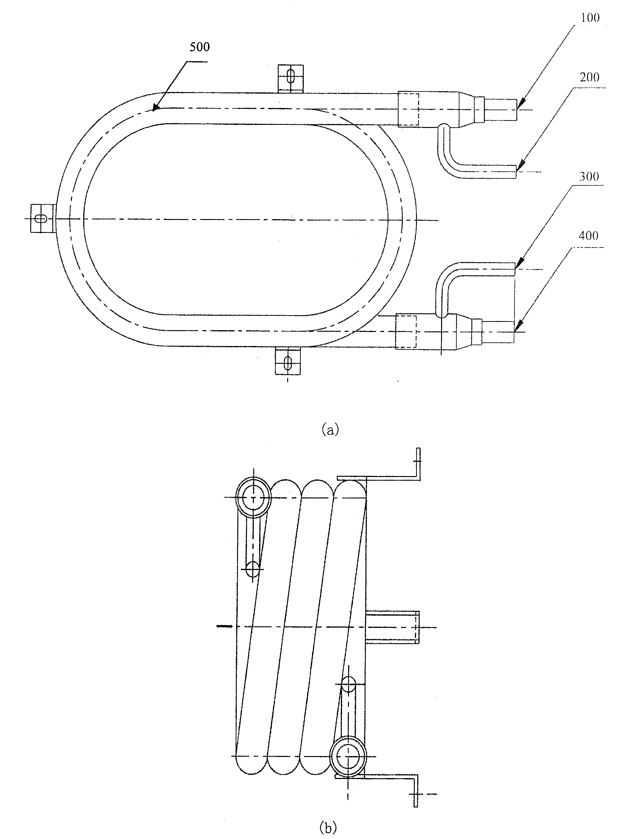
technical field [0001] The invention relates to a liquid-splitting casing condenser, which belongs to the technical field of thermal equipment. Background technique [0002] The sleeve condenser is a kind of thermal equipment, which is widely used in power, chemical industry, air-conditioning engineering and refrigeration engineering, such as refrigerators, freezers, and air-conditioning systems. [0003] figure 1 Shown is a conventional sleeve condenser consisting of concentric inner and outer tubes. Such as figure 1 , Figure (a) is a top view of a traditional sleeve condenser; Figure (b) is a side view of a traditional sleeve condenser. Among them, 100-refrigerant steam inlet, 200-cooling water outlet, 300-refrigerant condensate outlet, 400-cooling water inlet, 500-outer casing. In order to save space, the traditional sleeve condenser adopts a spiral arrangement, relying on the convective heat exchange between the cooling water in the gap between the sleeve and the inn...

Claims


Application Information

Patent Timeline
Patent Type & Authority Patents(China)
IPC IPC(8): F25B39/04
Inventor 彭晓峰吴迪陆规张扬
Owner TSINGHUA UNIV
Learn More