Liquid separating air condenser

A technology for air condensers and condensers, which is applied in steam/steam condensers, evaporators/condensers, refrigerators, etc., and can solve problems such as high manufacturing and operating costs, decreased utilization of fins, and poor condensation effects , to reduce production and operating costs, facilitate overall layout, and reduce thickness

Inactive Publication Date: 2007-06-06
TSINGHUA UNIV
View PDF0 Cites 44 Cited by
  • Summary
  • Abstract
  • Description
  • Claims
  • Application Information

AI Technical Summary

Problems solved by technology

During the condensation process, the liquid film gradually thickens, and in the long-term later, it will be a complex two-phase flow in which the liquid gradually increases, the thermal resistance will gradually increase, and the condensation effect will deteriorate seriously; at the same time, with the condensation of the steam, the amount of steam will gradually decrease. The steam flow rate in the tube drops significantly, the condensation effect degrades sharply, and the heat transfer coefficient decreases; the condensation process in a single tube process also leads to complex gas-liquid two-phase flow, which has great impact on system operation stability, flow resistance and system regulation. negative effect
On the air side, due to the increase in the thermal resistance of condensation heat transfer in the tube, the temperature of the outer tube wall decreases, resulting in a decrease in the utilization rate of the fins
In order to solve the above-mentioned problems, traditional air-cooled condensers increase the heat transfer area to meet the demand for heat transfer. The volume and weight are large, and the production and operation costs are high.

Method used


Image

  • Liquid separating air condenser
  • Liquid separating air condenser
  • Liquid separating air condenser

Examples


Embodiment Construction

[0024] Further illustrate the present invention below in conjunction with accompanying drawing.

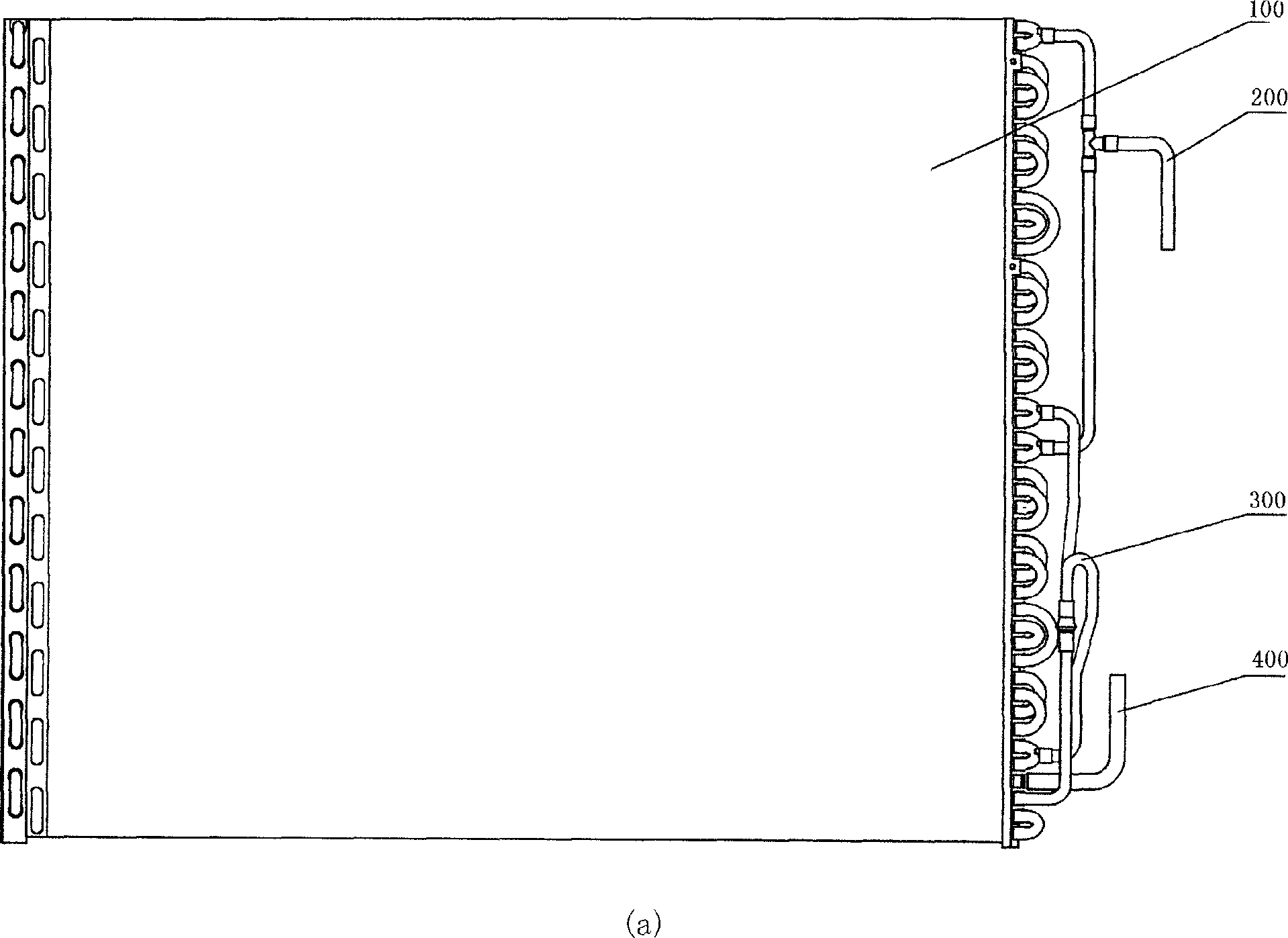
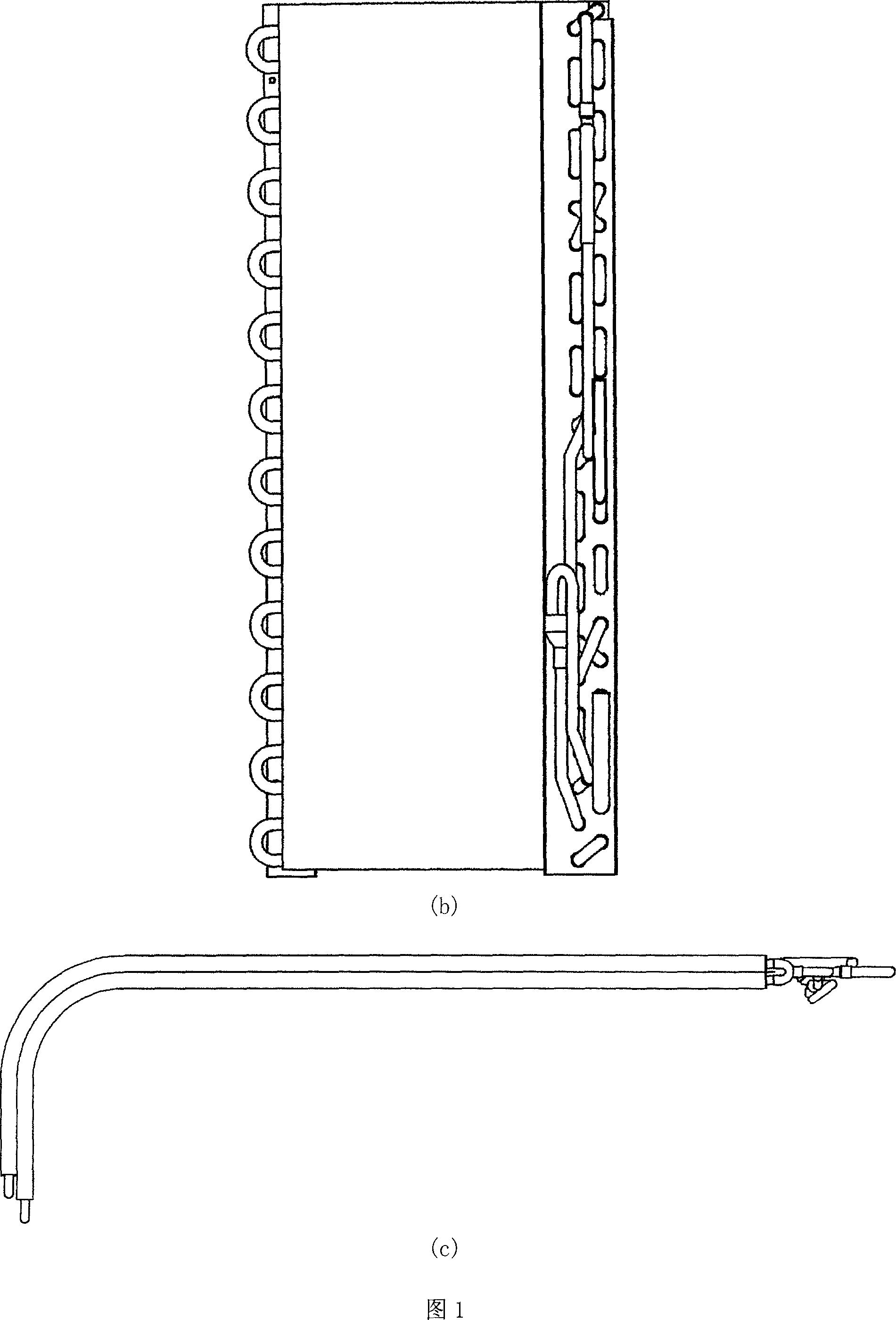
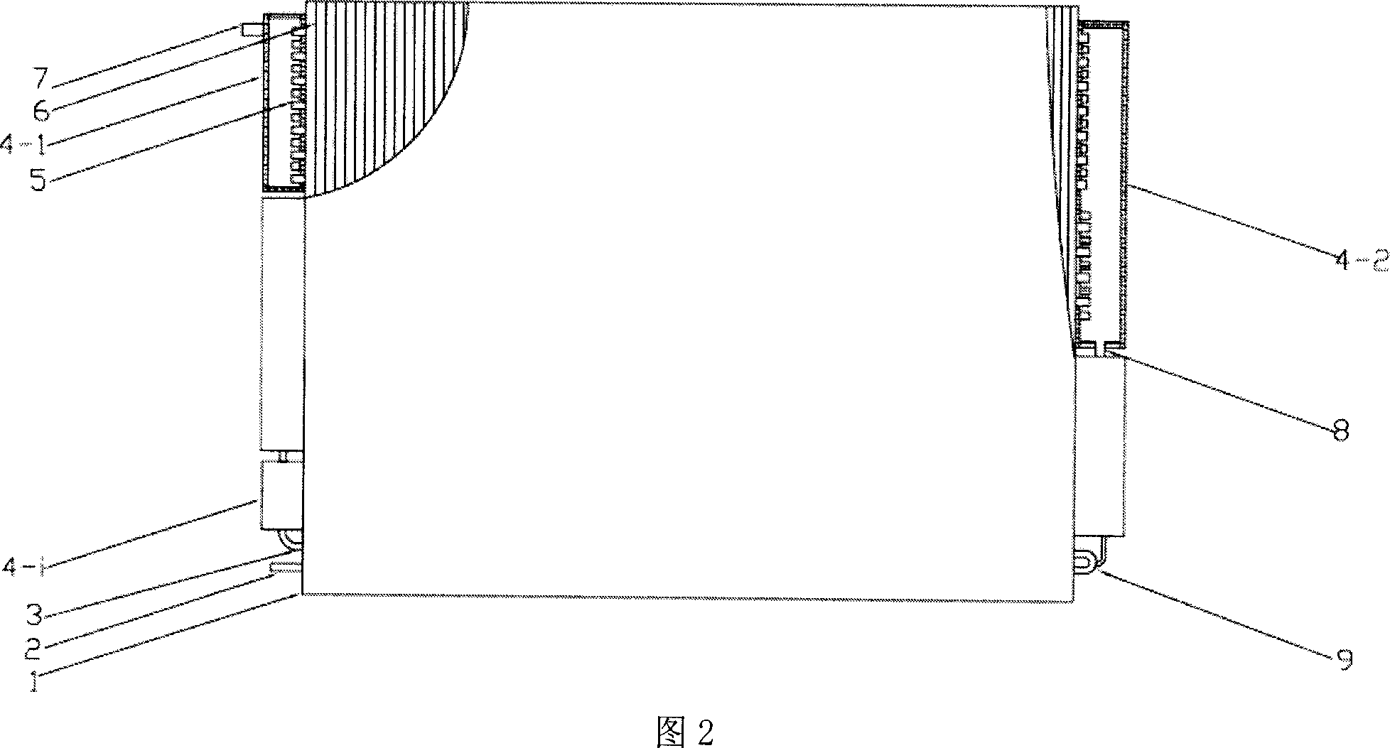
[0025] Fig. 2 is the front view of the present invention (horizontal tube type). Among them, 1 shell, 2 condensate outlet, 3 one-way pipe, 4-j cascade box j, 4-i last cascade box, 5 heat exchange tubes, 6 fins (fins), 7 steam inlet, 8 drain pipes, 9 tee pipes. A liquid separation type air condenser, comprising a steam inlet 7, a heat exchange tube 5, fins 6, a j-th cascade box 4-j, a drain pipe 8, a tee pipe 9, a condensate outlet 2, and a one-way exchange The heat pipe 3 and the shell 1; the jth cascade box (4-j) is installed at both ends of the heat exchange tube (5); the steam inlet (7) is connected to the first cascade box, and the first cascade box passes through a set of heat exchange The tube (5) communicates with the second cascade box; the second cascade box communicates with the next-level header through another set of heat exchange tubes (5); ...; until the last-level...


PUM


Abstract

A liquid-air-condenser belongs to thermal equipment technical fields. comprising steam inlet, heat exchange tube, fin, j cascade box, discharge pipe, three-limb tube, condensate outlet, single-pass pipe, shell; Steam from the steam inlet enter into the first cascade box and condense through the first group heat exchange tube, the vapor-liquid mixture flows into the second cascade box, vapor and liquid are separated: the liquid is ejected into the next cascade box by discharge pipes between cascade boxes , while steam enter into the next heat exchange tube group; collected by three-limb tube in the end and flow out through condensate outlet. The invention condense with stepped steam, separate by middle automatic vapor-liquid and drain fluid associate with super-cooling technology by the condensate concentrations, guarantee that each tube pass is entered with pure steam and cooled, effectively reduce the thickness of the liquid film in condensation process and eliminate the adverse biphasic flow pattern; compared with traditional condenser, save 30% material and reduce the condenser production and operation cost, and simple in production.

Description

technical field [0001] The invention relates to a liquid separation type air condenser, which belongs to the technical field of thermal equipment. Background technique [0002] Air condenser is a kind of thermal equipment, which is widely used in power, chemical industry, air conditioning engineering and refrigeration engineering, such as refrigerators, freezers, automobiles, and thermal power plants. [0003] Figure 1 shows a conventional air conditioner air condenser. As shown in Figure 1, Figure (a) is a front view of a traditional air condenser; Figure (b) is a top view of a traditional air condenser; Figure (c) is a side view of a traditional air condenser. Among them, 100-shell, 200-steam inlet, 300-tee pipe, 400-condensate outlet. Traditional air condensers mostly adopt coiled tube type, relying on the convective heat transfer of air outside the tube, and the refrigerant vapor condenses inside the tube. The inlet of the condensing tube of this air-cooled condenser ...

Claims


Application Information

Patent Timeline
Patent Type & Authority Applications(China)
IPC IPC(8): F28B1/06F28F9/02F25B39/04
Inventor 彭晓峰吴迪陆规王珍黄梅
Owner TSINGHUA UNIV
Why Eureka
Try Eureka