Assistant glue dispensing equipment

A technology of auxiliary points and lens barrels, applied in installation, optics, instruments, etc., can solve problems such as positioning unit displacement, striker, and shaft eccentricity

Inactive Publication Date: 2010-01-20
HONG FU JIN PRECISION IND (SHENZHEN) CO LTD +1
View PDF4 Cites 0 Cited by
  • Summary
  • Abstract
  • Description
  • Claims
  • Application Information

AI Technical Summary

Problems solved by technology

However, during the rotation process, the rotation shaft will inevitably be eccentric, so that the positioning unit may have a displacemen

Method used


Image

  • Assistant glue dispensing equipment
  • Assistant glue dispensing equipment
  • Assistant glue dispensing equipment

Examples


Embodiment Construction

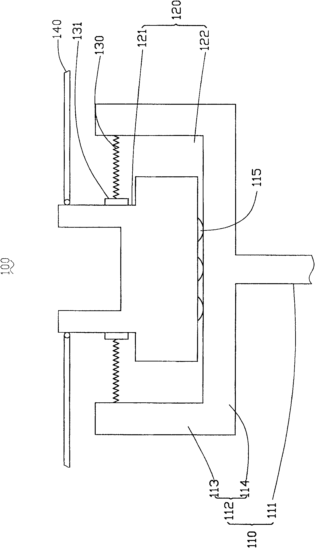
[0012] The technical solution will be further described in detail below in conjunction with the accompanying drawings and embodiments.

[0013] Such as figure 1 As shown, the embodiment of the technical solution provides an auxiliary dispensing device 100 , which includes a rotating stage 110 , a lens barrel fixing mechanism 120 , at least one elastic connecting body 130 and a positioning member 140 . The rotating stage 110 includes a rotating shaft 111 and a supporting portion 112 , the rotating shaft 111 is perpendicular to the supporting portion 112 and is arranged on the axis of the supporting portion 112 . The lens barrel fixing mechanism 120 is disposed on the support portion 112 of the rotary stage 110 . The lens barrel fixing mechanism 120 can be arranged coaxially with the supporting part 112 or not, as long as the lens barrel fixing mechanism 120 can rotate by itself through the rotation of the rotating shaft 111 . In this embodiment, the lens barrel fixing mechani...


PUM


Abstract

The invention comprises a rotary carrier table, a lens barrel fixing mechanism, at least one elastic connection body and a positioning component. Said lens barrel fixing mechanism is located at the surface of the rotary table; one end of the elastic is secured on the rotary table, and the other end is used for supporting the lens barrel fixing mechanism. Said positioning component is used for positioning the location of the lens barrel fixing mechanism during rotation.

Description

technical field [0001] The invention relates to the technical field of glue dispensing, in particular to an auxiliary glue dispensing device used in the lens module assembly process. Background technique [0002] A lens module applied to a camera or an optical instrument usually includes a lens mount, a lens barrel, a lens group, a spacer ring and a filter. Wherein, the lens group, the spacer ring and the optical filter are sequentially fixed in the lens barrel along the direction of the optical axis, and the spacer ring and the optical filter are fixed together. The outer wall of the lens barrel and the inner wall of the lens holder are usually provided with matching threads, and the lens barrel is screwed into the lens holder through the threads to be fixed. [0003] During the assembly process of the lens module, the optical filter and the spacer ring are generally fixed by a dispensing process. The glue dispenser used in the glue dispensing process usually includes a g...

Claims


Application Information

Patent Timeline
IPC IPC(8): G02B7/02
Inventor 凌维成
Owner HONG FU JIN PRECISION IND (SHENZHEN) CO LTD
Why Eureka
Try Eureka