Supercharge Your Innovation With Domain-Expert AI Agents!

CCD camera assembly and plane display device

A camera component and flat display technology, applied in electrical components, image communication, color TV components, etc., can solve the problem of small shooting angle range

Inactive Publication Date: 2010-01-20
INNOCOM TECH SHENZHEN +1
View PDF4 Cites 0 Cited by
  • Summary
  • Abstract
  • Description
  • Claims
  • Application Information

AI Technical Summary

Problems solved by technology

[0007] In order to solve the problem that the shooting angle range of the camera assembly of the flat display device in the prior art is small, it is necessary to provide a camera assembly with a large shooting angle range

Method used


Image

  • CCD camera assembly and plane display device
  • CCD camera assembly and plane display device
  • CCD camera assembly and plane display device

Examples


Embodiment Construction

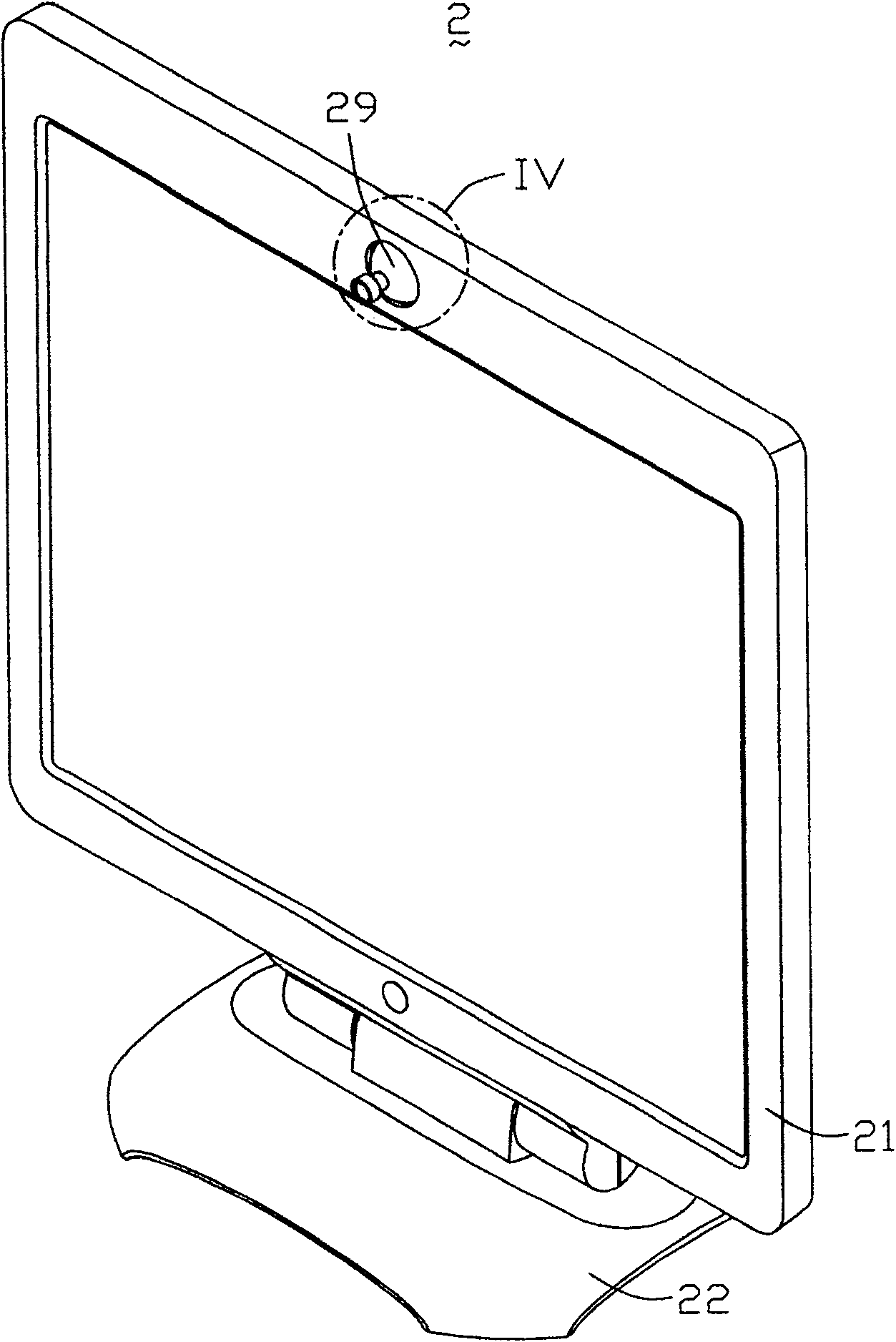
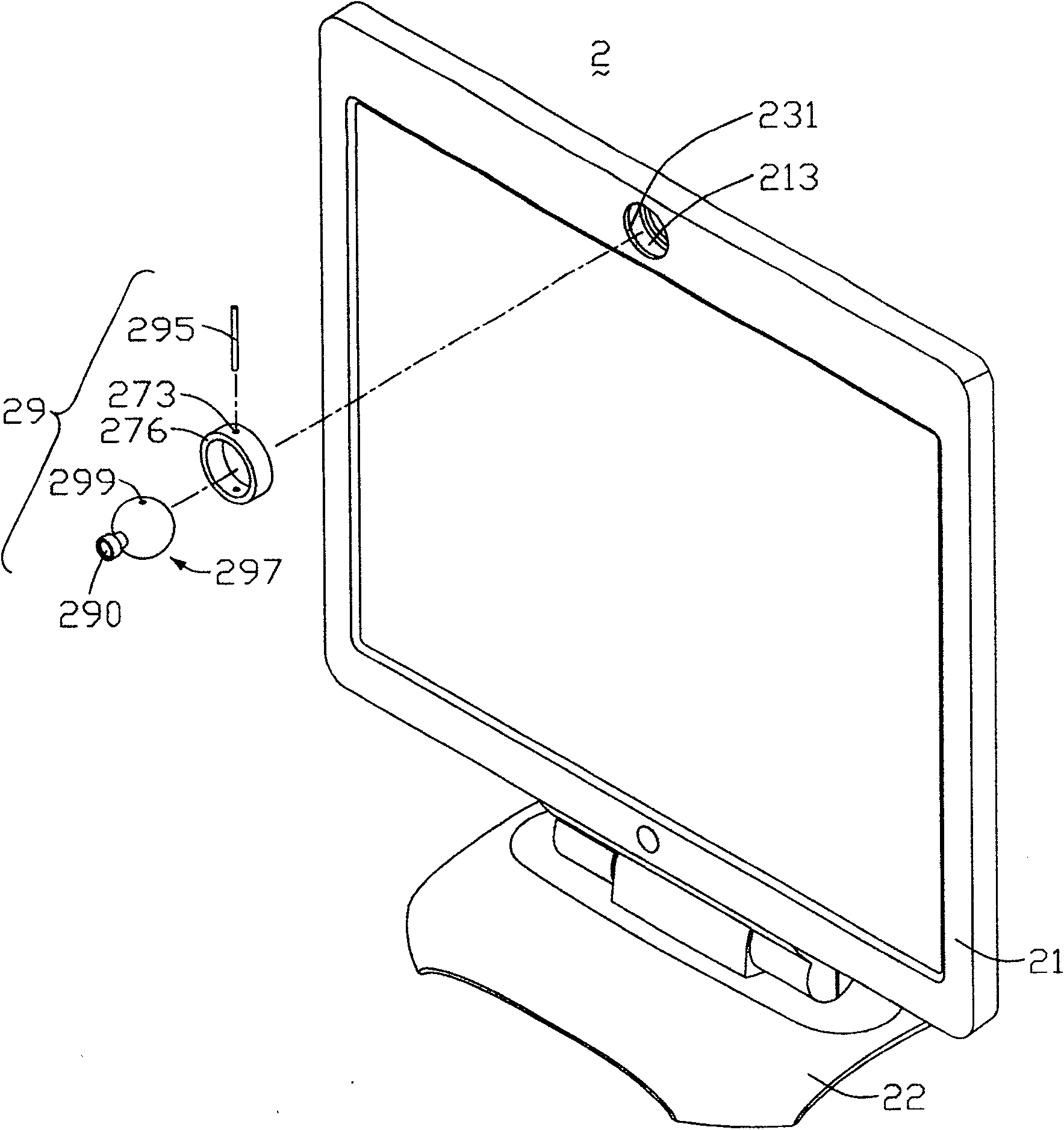
[0019] Please also refer to figure 2 , image 3 and Figure 4 , figure 2 It is a three-dimensional schematic diagram of the first embodiment of the flat panel display device of the present invention, image 3 is an exploded schematic view of the flat panel display device, Figure 4 yes figure 2 Partial enlarged view of IV in middle. The flat panel display device 2 includes a display body 21 , a base 22 and a camera assembly 29 . The base 22 supports and fixes the display body 21 , and the camera assembly 29 is disposed on the top of the display body 21 . The display body 21 can be a liquid crystal display body.

[0020] The display body 21 is generally rectangular and includes a frame (not shown). A cylindrical through hole 231 is formed in the middle of the upper part of the frame. The inner surface of the through hole 231 has a circular guide rail 213 .

[0021] The camera assembly 29 includes a camera 297 , a shaft 295 and a ring 276 . The camera 297 is generall...


PUM


Abstract

The invention relates to a camera component and a plane display device used for the camera component. The plane display device comprises a display body and a camera component. The display body comprises a cylindrical through-hole; the internal side of the through-hole is provided with an annular guide track. The camera component comprises a camera lens and a shaft body. The two ends of the shaft body are arranged in the annular guide track and can rotate around the central shaft of the annular guide track; the camera lens is pivoted with the shaft body and can rotate around the shaft body in the plane vertical to the shaft body; the camera can be arranged in front of the display body to provide the shooting in any direction so as to meet the requirements of users.

Description

technical field [0001] The invention relates to a camera assembly and a plane display device using the camera assembly. Background technique [0002] In recent years, flat panel display devices have gradually replaced traditional cathode ray tube display devices due to their advantages of being light and thin and occupying less space, and have gradually occupied the mainstream of display products. [0003] see figure 1 , is a three-dimensional schematic diagram of a prior art flat display device. The flat panel display device 1 includes a display body 11 , a base 12 and a camera assembly 19 . The base 12 supports and fixes the display body 11 , and the camera assembly 19 is disposed on the top of the display body 11 . [0004] The display body 11 is generally rectangular, with a rectangular notch 113 disposed in the middle of the upper portion thereof, and opposite side walls (not shown) of the rectangular notch 113 are provided with two axial holes 115 opposite to each o...

Claims


Application Information

Patent Timeline
Patent Type & Authority Patents(China)
IPC IPC(8): G06F1/16H04N5/225
Inventor 卢月芹周通
Owner INNOCOM TECH SHENZHEN
Features
  • R&D
  • Intellectual Property
  • Life Sciences
  • Materials
  • Tech Scout
  • Unparalleled Data Quality
  • Higher Quality Content
  • 60% Fewer Hallucinations
Learn More