Fundus observation device

A technology of fundus observation and components, which is applied in the direction of ophthalmoscopes, measuring devices, and optical devices, etc., can solve problems such as low accuracy, difficulty in fully correcting, and differences in signal light dispersion and dispersion effects, and achieve high precision and high interference efficiency. Effect

Inactive Publication Date: 2007-07-18
KK TOPCON
View PDF4 Cites 12 Cited by
  • Summary
  • Abstract
  • Description
  • Claims
  • Application Information

AI Technical Summary

Problems solved by technology

[0039] However, in the case where the optical system of the fundus camera is used to guide the signal light, since the signal light passes through more optical components than in conventional optical image measuring devices, the signal light and The interference efficiency of the reference light is reduced, and it may be difficult to generate sufficient intensity of interference light
When an image is formed by such insufficiently intense interference light, the OCT image may have problems such as a low-contrast and unclear image or a low-precision image.
[0040] In the previous optical image measuring device, the difference in the influence of dispersion of the signal light and the reference light, although there are corrections and other treatments in the image processing
However, in the fundus observation device that can capture the fundus image by the fundus camera and obtain the fundus image by the optical image measuring device, the number of optical components through which the signal light passes is very different from the number of optical components that the reference light passes through. Therefore, the dispersion effect on the signal light is also very different from the dispersion effect on the reference light, so it is difficult to fully correct it in image processing

Method used


Image

  • Fundus observation device
  • Fundus observation device
  • Fundus observation device

Examples


Embodiment Construction

[0092] Hereinafter, a fundus observation device according to an example of an embodiment of the present invention will be described in detail with reference to the drawings. In addition, the same reference numerals as in Figs. 9 and 10 are used for the same components as before.

[0093]

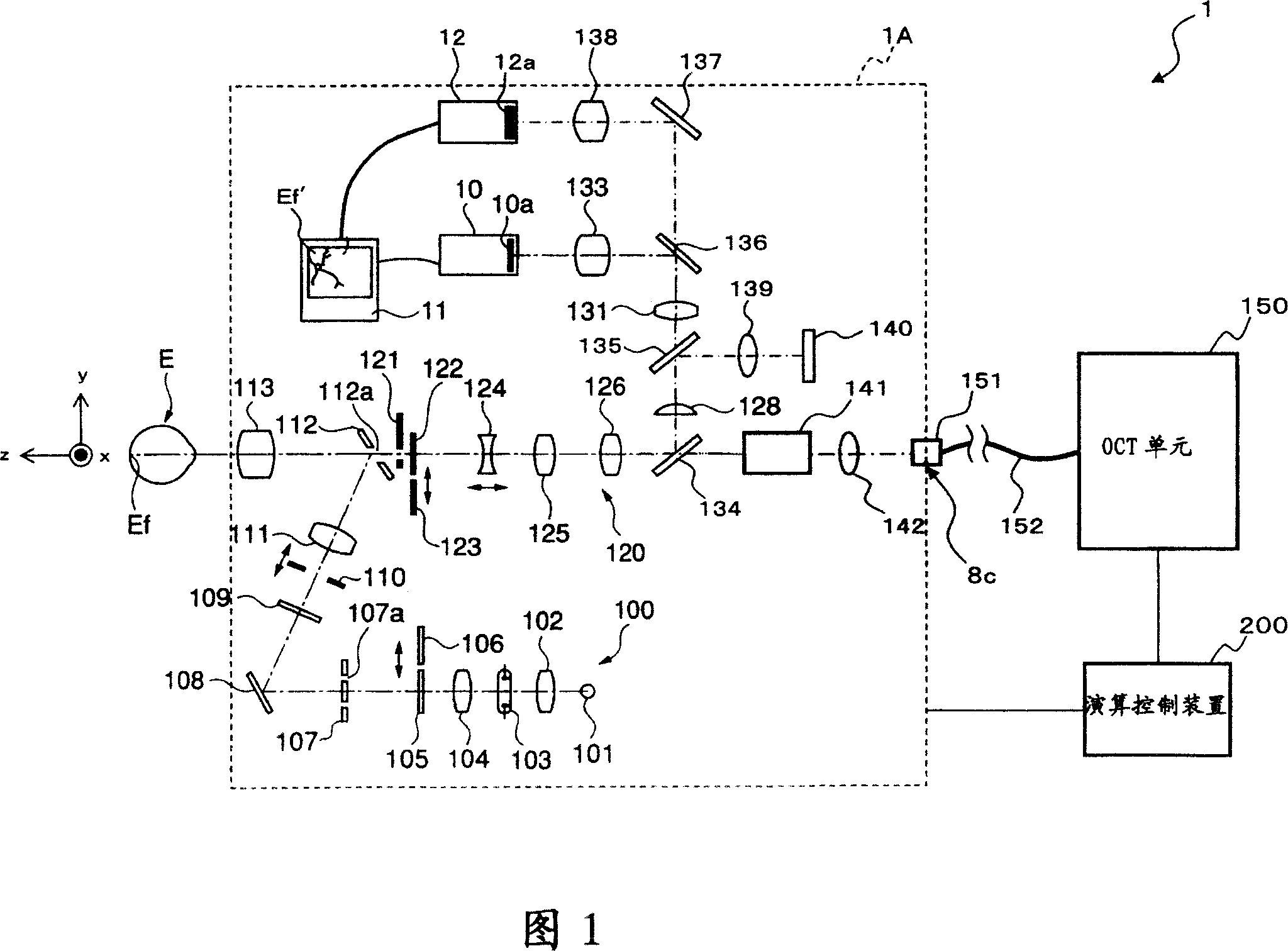
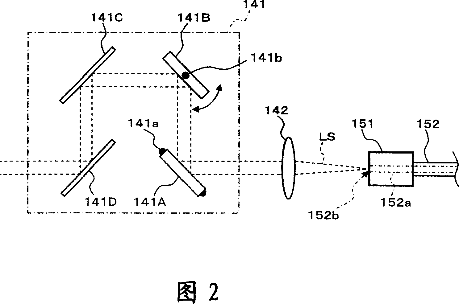
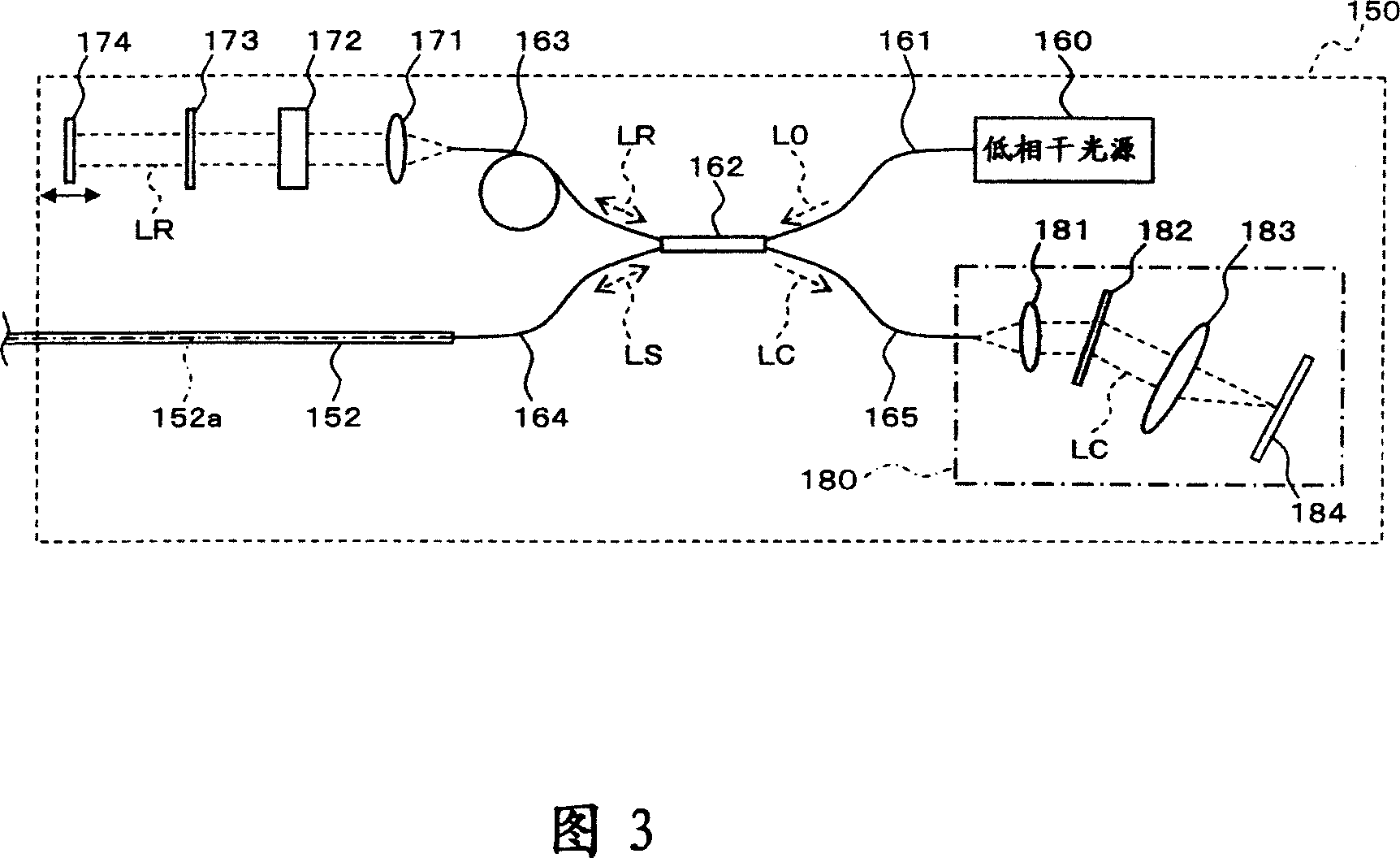
[0094] First, the configuration of a first embodiment of the fundus observation device of the present invention will be described with reference to FIGS. 1 to 5 . FIG. 1 shows the overall configuration of a fundus observation device 1 according to this embodiment. FIG. 2 shows the configuration of the scanning unit 141 in the fundus camera unit 1A. FIG. 3 shows the structure of the OCT unit 150 . FIG. 4 shows the hardware configuration of the arithmetic control device 200 . FIG. 5 shows the structure of the control system of the fundus observation device 1 .

[0095] the whole frame

[0096] As shown in FIG. 1 , the fundus observation device 1 includes a fundus camera unit 1A functio...


PUM


Abstract

A fundus observation device which can simultaneously capture both surface images and tomographic images of the fundus oculi is provided. The fundus observation device (1) has a fundus camera unit (1A), an OCT unit (150), and an arithmetic and control unit (200). The fundus camera unit (1A) has an illuminating optical system (100) and an imaging optical system (120). The arithmetic and control unit (200) forms the surface image of fundus oculi Ef based on signals from fundus camera unit (1A). The OCT unit (150) divides low coherence light LO into the signal light LS and the reference light LR, and detects the interference light LC that can be obtained from the signal light LS passing through fundus oculi Ef and the reference light LR passing through reference mirror (174). The arithmetic and control unit (200) forms tomographic images of fundus oculi Ef based on these detecting results. A Dichroic mirror (134) combines the optical path of the signal light LS toward fundus oculi Ef into the optical path for imaging of the imaging optical system (120), and separates the optical path of the signal light LS towards fundus oculi Ef from the optical path for imaging.

Description

technical field [0001] The present invention relates to a fundus observation device for observing the state of the fundus of an eye to be inspected. Background technique [0002] As a fundus observation device, a fundus camera has conventionally been widely used. FIG. 9 shows an example of an external configuration of a conventional general fundus camera, and FIG. 10 shows an example of an optical system built therein (for example, refer to Japanese Patent Laid-Open No. 2004-350849). In addition, the term "observation" includes at least observation of a captured image of the fundus (in addition, observation of the fundus with the naked eye may also be included). [0003] First, the appearance structure of a conventional fundus camera 1000 will be described with reference to FIG. 10 . The fundus camera 1000 includes a gantry 3 mounted on a base 2 so as to be slidable in front, rear, left, and right directions (horizontal directions). An operation panel and a control lever ...

Claims


Application Information

Patent Timeline
IPC IPC(8): A61B3/12A61B3/14G01B9/02
Inventor 福间康文大塚浩之弓挂和彦
Owner KK TOPCON
Why Eureka
Try Eureka