Cylinder lock

A ball lock and lock head technology, applied in cylinder ball locks, locks with turning keys, building locks, etc., can solve the problems of large diameter of the lock body and increased production cost, and achieve the effect of reducing production costs and saving materials.

Active Publication Date: 2007-07-18
雷先鸣
View PDF1 Cites 0 Cited by
  • Summary
  • Abstract
  • Description
  • Claims
  • Application Information

AI Technical Summary

Problems solved by technology

Since the locking side column is inserted into the lock body in the radial direction of the lock cylinder to prevent the lock cylinder from rotating, this requires a larger diameter of the lock body, resulting in the use of more materials and increased production costs.

Method used


Image

  • Cylinder lock

Examples


Embodiment Construction

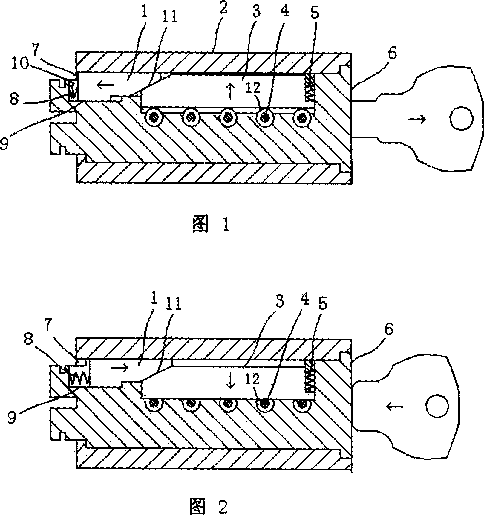
[0010] See Fig. 1, the lock head of the tumbler lock of the present invention is based on the lock head disclosed in the ZL99115581. The V-shaped groove 12 on the marble 4 in the 6 is matched, and the chute 9 communicating with the locking side post groove is set on the lock core 3. The chute 9 extends axially to the tail of the lock core and has an end wall 10. Sliding block 1 is placed in groove 9, and between sliding block 1 and locking side post 3, be inclined plane 11 contact, between end wall 10 in chute 9 and sliding block 1, sliding block reset spring 8 is set, and at the end of lock body 2 There is a notch 7 corresponding to the lock cylinder chute 9 on the step for stopping the lock cylinder, and the sliding block 1 in the chute 9 can cooperate with the notch 7 .

[0011] working principle:

[0012] As shown in Figure 1, when the lock head of the present invention is in the locked state, the V-shaped groove 12 on the V-shaped groove pin 4 in the lock core 6 is not i...


PUM


Abstract

The locking head for cylinder lock includes one lock body, one lock core and one locking side pin inside the lock core to match the V-slotted marble. The lock core has a runner communicated with the locking side pin, a sliding block inside the runner contacting with the locking side pin, a block restoring spring. The lock body has notch in the tail for matching the sliding block. The present invention realizes the combination and separation of the lock core and the lock body by means of the axial motion of the sliding block, and may have locking head with reduced diameter, less material consumption and lowered production cost.

Description

technical field [0001] The invention belongs to mechanical locks, and relates to a lock head of a pin lock. Background technique [0002] Regarding the lock head of the tumbler lock, there is a lock head in the prior art that uses the locking side column to cooperate with the pin with the V-shaped groove in the lock cylinder to control the opening and closing of the lock, see ZL99115581.5 patent document. Although this lock has the characteristics of better anti-theft and anti-technical unlocking. However, there are also some shortcomings. Since the locking side posts are inserted into the lock body in the radial direction of the lock core to prevent the lock core from rotating, this requires a larger diameter of the lock body, resulting in the use of more materials and increased production costs. Contents of the invention [0003] The object of the present invention is to provide a lock head of a tumbler lock which saves material and reduces production cost in view of t...

Claims


Application Information

Patent Timeline
Patent Type & Authority Applications(China)
IPC IPC(8): E05B27/06E05B35/00E05B19/08E05B15/00
Inventor 雷先鸣
Owner 雷先鸣
Why Eureka
Try Eureka