Sealing component

A technology of sealing components and sealing lips, which is applied in the direction of engine components, engine sealing, mechanical equipment, etc., can solve the problems of difficult processing and production, and the inability to add oil return channels, etc.

Inactive Publication Date: 2007-07-18
昆山茂顺密封件工业有限公司
View PDF0 Cites 3 Cited by
  • Summary
  • Abstract
  • Description
  • Claims
  • Application Information

AI Technical Summary

Problems solved by technology

[0005] Please refer to Fig. 6 and Fig. 7 again. Through actual tests, it is found that when the number of oil return channels increases or the angle of oil return channels becomes smaller, the measured oil return rate is higher, but the oil return rate of the oil return channels is higher. If the groove angle is too small, it is not only difficult to process and manufacture, but it is also easier to add a large number of oil return grooves because the oil return grooves arranged along the circumference are too close to each other. Generally speaking, when the oil return groove angle θ of the oil return groove When the angle is less than 22.5 degrees, the above-mentioned deficiency will occur. Therefore, although the aforementioned sealing element 4 can reduce the loss of lubricating oil, there is still room for improvement in its oil return effect

Method used


Image

  • Sealing component
  • Sealing component
  • Sealing component

Examples


Embodiment Construction

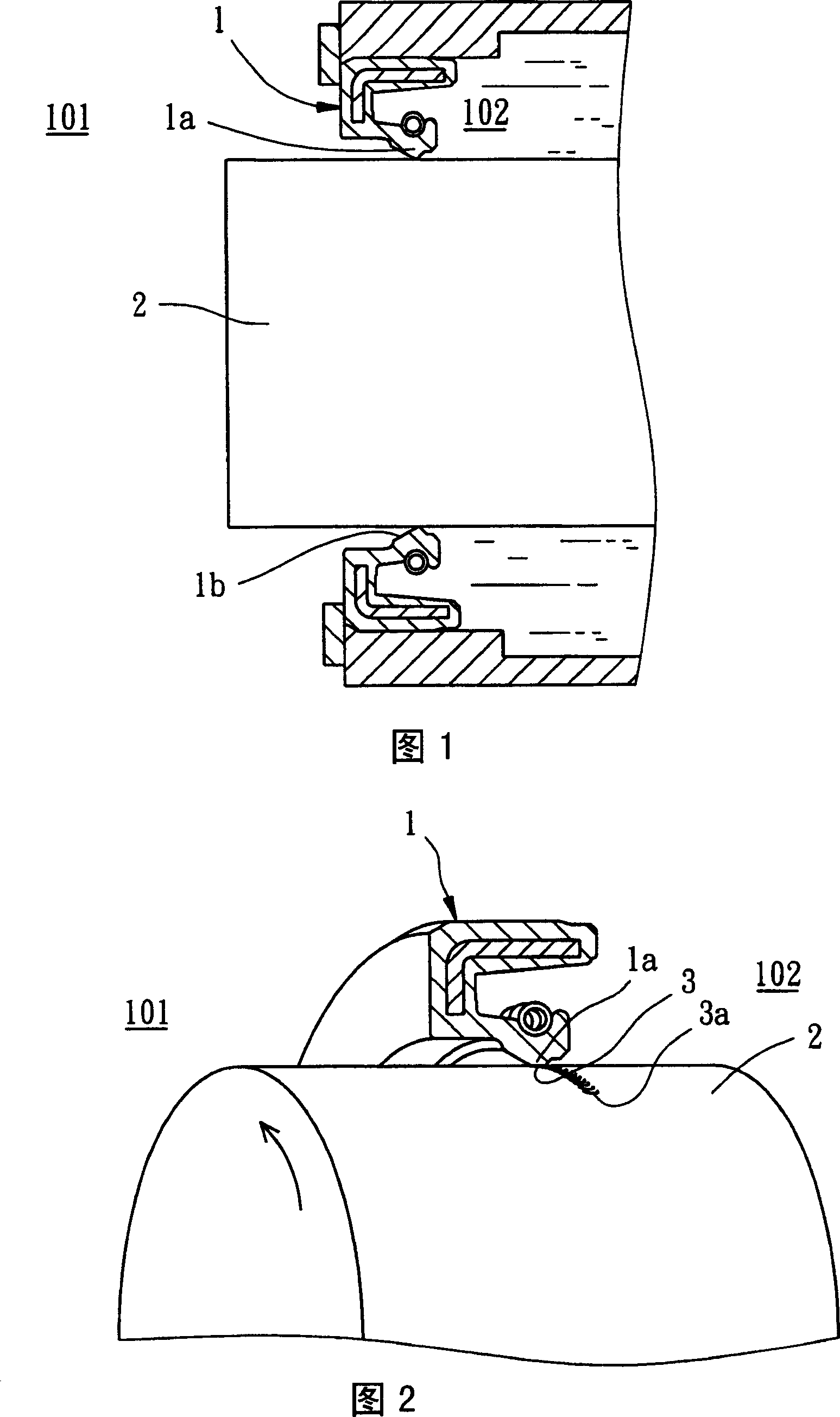
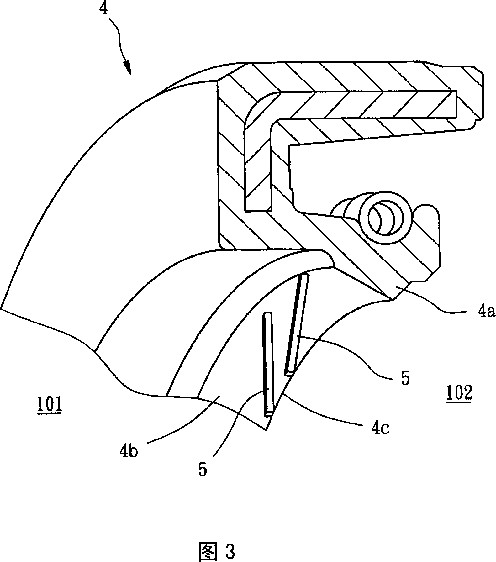
[0048] 8 and 9 are schematic diagrams of an application example of a sealing element 100 in a preferred embodiment of the present invention, revealing that the sealing element 100 is sleeved on a rotating shaft 200 rotating counterclockwise, and is located between the rotating shaft 200 and an oil groove. 300 , which is mainly used to isolate the air from the lubricating oil in the oil tank 300 , one side of the sealing element 100 is the air side 101 , and the other side is the oil side 102 .

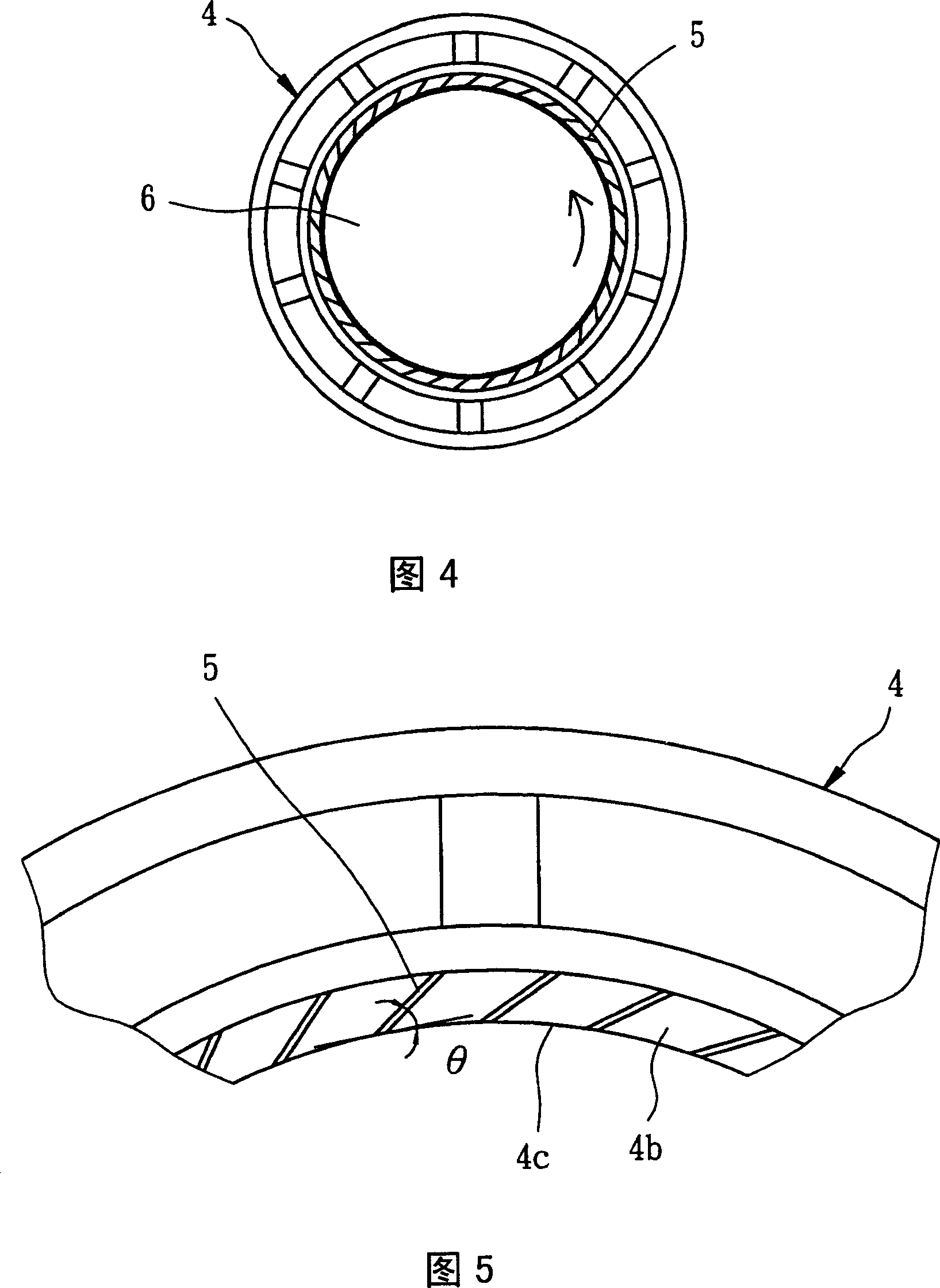
[0049] Please refer to FIG. 10 , the sealing element 100 of the foregoing embodiment includes a circular frame body 10, an annular body 12, a sealing lip 14, a spring ring 16 and a plurality of oil return grooves 18, wherein the annular body 12, the sealing The lip 14 and the oil return groove 18 are integrally formed of rubber material, and the structure of each part is described below:

[0050] The circular frame body 10 is made of metal and serves as the main support body of the sea...


PUM


Abstract

The invention is a sealing component, jacketed on a rotating shaft and having a sealing lip butted against the surface of the rotating shaft to isolate air from lubricant, where one side of the sealing lip facing external air is equipped with plural oil return grooves formed by salience, which are designed in two-segment turning mode, able to effectively block leakage lubricant and push the lubricant back to reduce lubricant loss.

Description

technical field [0001] The present invention relates to an element sheathed on a rotary shaft (r. tary shan) for isolating air and lubricating oil, more specifically, it refers to a sealing element with high oil return effect. Background technique [0002] Fig. 1 is a kind of lip type seal (lip type seal) 1, and this sealing element 1 has a radially protruding rubber lip 1a. The rubber lip 1a is pressed against the rotating shaft 2 and deformed so as to effectively isolate the air and lubricating oil. Herein, the two sides of the sealing element 1 are respectively an air side 101 and an oil side 102, The function of the sealing element 1 is to prevent the lubricating oil from the oil side 102 from overflowing to the air side 101 . [0003] Please refer to Figure 2, when the above-mentioned sealing element 1 is actually used, there will be an oil film 3 between the rubber lip 1a and the rotating shaft 2, the oil film 3 can not only have a sealing effect but also maintain the...

Claims


Application Information

Patent Timeline
Patent Type & Authority Applications(China)
IPC IPC(8): F16J15/32F16J15/3208F16J15/3284
Inventor 温志涌杨安石李彦霆萧邦佶曾俊翔
Owner 昆山茂顺密封件工业有限公司
Why Eureka
Try Eureka