

Power transmission apparatus
a transmission apparatus and power technology, applied in mechanical devices, gearing details, gearing chambers, etc., can solve the problems of poor oil return from the clutch chamber at the two sides to the gear chamber in the center, difficult to keep the oil surface of the gear chamber at a higher position, and the risk of mixing the oil sucked from the suction opening of the oil strainer with air (aeration)
- Summary
- Abstract
- Description
- Claims
- Application Information
AI Technical Summary
Benefits of technology
Problems solved by technology
Method used
Image

Examples
Embodiment Construction
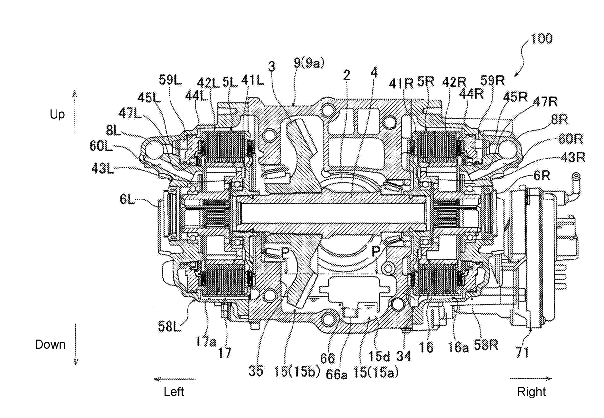
[0016]The disclosure is directed to provide a power transmission apparatus that can prevent an oil surface in the gear chamber from excessively decreasing by means of improving an oil return performance from clutch chambers to a gear chamber, and can effectively prevent oil sucked from a suction opening of an oil strainer from being mixed with air (aeration).
[0017]To achieve the objective, the power transmission apparatus of an embodiment of the disclosure is a power transmission apparatus (100) mounted on a vehicle, and characterized by including: a rotating shaft (4), extending along a width direction of the vehicle, and used for transmitting power to a drive wheel of the vehicle; gears (2, 3), disposed on the rotating shaft (4), and used for transmitting power to the rotating shaft (4); a clutch (5R or 5L), used for disconnecting or connecting the power transmitted by the rotating shaft (4) to the drive wheel; a gear chamber (15), used for accommodating the gears (2, 3), a clutch...
PUM
 Abstract
Description
Claims
Application Information