Check patentability & draft patents in minutes with Patsnap Eureka AI!

Backlight module

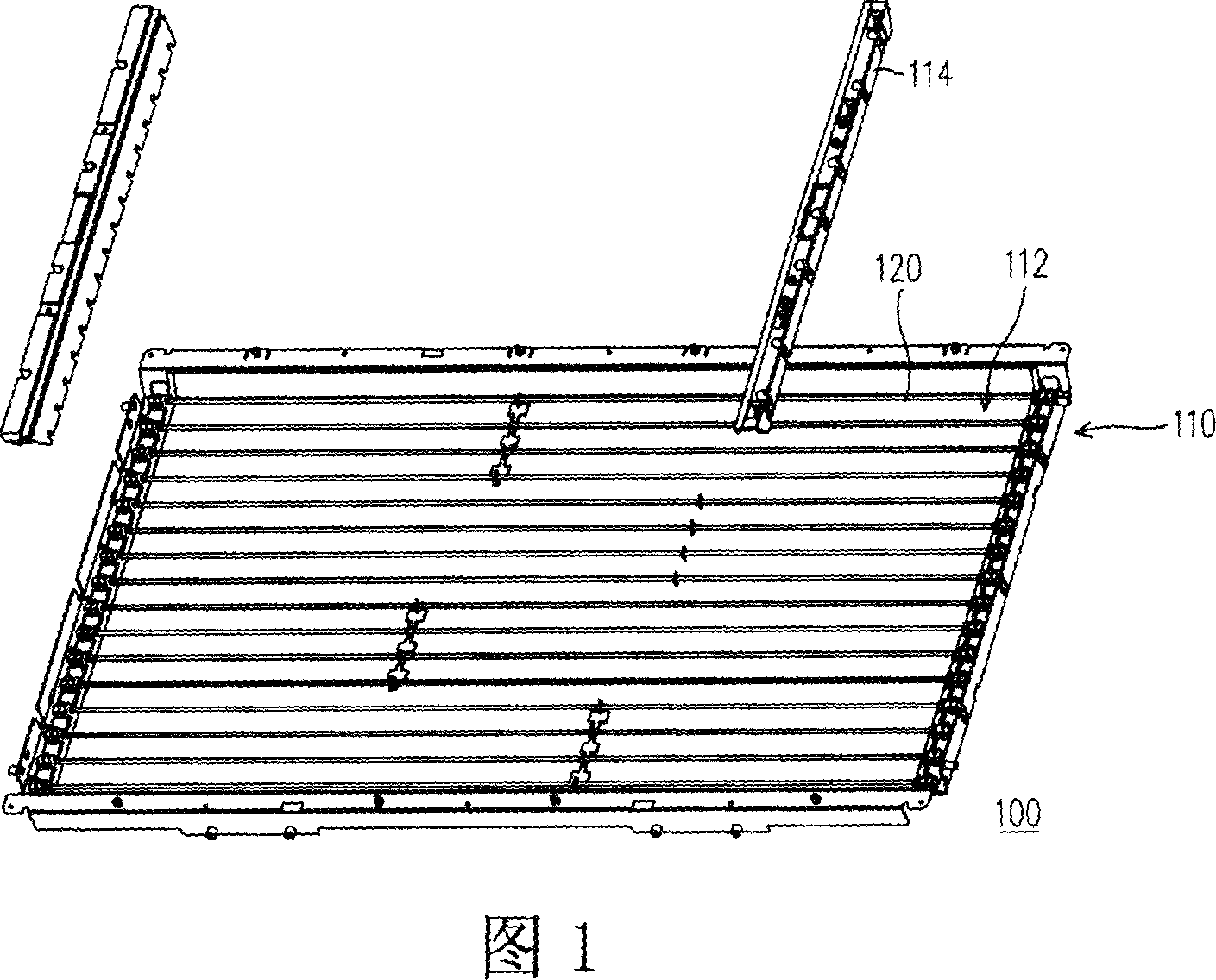
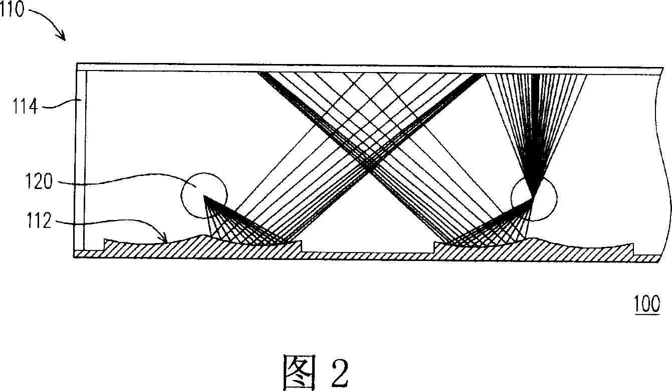
A backlight module and light source technology, applied in optics, nonlinear optics, instruments, etc., can solve the problems of bending the lamp tube 120, affecting the optical effect of the display, etc., and achieve the effect of preventing lamp tube deformation and saving costs.

Inactive Publication Date: 2007-07-18
AU OPTRONICS CORP
View PDF0 Cites 1 Cited by
  • Summary
  • Abstract
  • Description
  • Claims
  • Application Information

AI Technical Summary

Problems solved by technology

However, in order to be applied to a large-sized display, the size of the backlight module 100 also becomes larger. If this method of placing the lamp tube 120 is used, the lamp tube 120 is likely to be bent due to the influence of gravity, thereby affecting the optical effect of the display.

Method used


Image

  • Backlight module
  • Backlight module
  • Backlight module

Examples


Embodiment Construction

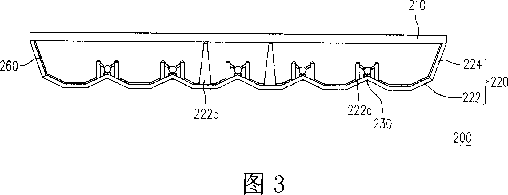
[0036] FIG. 3 is a cross-sectional view of the backlight module of the present invention, and FIG. 4 is an exploded perspective view of the backlight module of FIG. 3 . Please refer to FIG. 3 and FIG. 4 at the same time, the backlight module 200 includes a diffusion plate 210 , a frame 220 and at least one light source 230 . The frame 220 is disposed on one side of the diffusion plate 210 , wherein the diffusion plate 210 is placed on the frame 220 . The frame 220 has a wave-shaped bottom plate 222 and a side plate 224 , wherein the wave-shaped bottom plate 222 is connected to the side plate 224 . In this embodiment, the wave-shaped bottom plate 222 and the side plate 224 are integrally formed, and the material of the wave-shaped bottom plate 222 may be resin. In addition, the corrugated bottom plate 222 and the side plate 224 may not be integrally formed. In other words, the side plate 224 can be made of metal or other materials, and the side plate 224 can be connected to t...


PUM


Abstract

A backlight module is prepared as setting frame at one side of diffusion plate and forming said frame by a wave shaped base plate and a side plate, setting multiple light source support seat on wave shaped base plate and integrating said seats with said base plate to be a unified body, setting light source between wave shaped base plate and diffusion plate.

Description

technical field [0001] The invention relates to a display, and in particular to a backlight module of the display. Background technique [0002] With the development of technology, digital tools such as mobile phones, digital cameras, digital video cameras, notebook computers and desktop computers are all becoming more convenient and multifunctional. And beautiful direction development. When using these information products, the display screen is an indispensable human-machine communication interface. Through the display function of the display screen, the user can operate the product more conveniently. Liquid crystal displays have become the mainstream of display screens due to their advantages of power saving and low radiation. However, since the liquid crystal display panel of the liquid crystal display itself cannot emit light, a backlight module must be provided under the liquid crystal display panel to provide a light source to achieve the display function. [0003]...

Claims


Application Information

Patent Timeline
Patent Type & Authority Applications(China)
IPC IPC(8): G02F1/1335G02F1/1333
Inventor 李南庆蔡宗光蔡淑慧
Owner AU OPTRONICS CORP
Features
  • R&D
  • Intellectual Property
  • Life Sciences
  • Materials
  • Tech Scout
  • Unparalleled Data Quality
  • Higher Quality Content
  • 60% Fewer Hallucinations
Learn More