Torque transmission structure, traction drive transmission device, and steering device for vehicle

A speed change device, traction transmission technology, applied in the direction of transmission device, friction transmission device, belt/chain/gear, etc., can solve the problems that cannot be realized

Inactive Publication Date: 2007-07-25
MITSUBISHI HEAVY IND LTD
View PDF3 Cites 5 Cited by
  • Summary
  • Abstract
  • Description
  • Claims
  • Application Information

AI Technical Summary

Problems solved by technology

[0008] However, in the above-mentioned existing traction transmission transmission or planetary gear transmission, since the input-output transmission ratio is a predetermined linear transmission, it is impossible to realize a linear transmission ratio different from the preset linear transmission ratio in one transmission. any gear ratio
[0009] In addition, the steering device for a vehicle, which sets the transmission ratio of the entire steering system to a desired value by interposing the speed increaser and the speed reducer in the torque transmission system, etc., is considered to be installed in a limited space of the vehicle. Since the speed increaser and reducer are arranged on the same shaft and elongate in the axial direction, there is a problem in miniaturization

Method used


Image

  • Torque transmission structure, traction drive transmission device, and steering device for vehicle
  • Torque transmission structure, traction drive transmission device, and steering device for vehicle
  • Torque transmission structure, traction drive transmission device, and steering device for vehicle

Examples


no. 1 approach

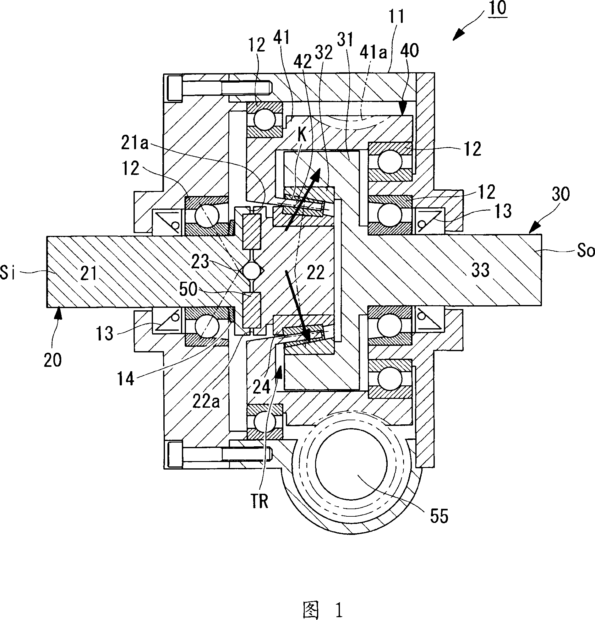
[0082] FIG. 1 is a cross-sectional view showing a first embodiment of a traction transmission transmission according to the present invention. This traction transmission transmission device (hereinafter referred to as "transmission device") 10 has the function of changing the rotational speed of the input shaft Si to a desired gear ratio by utilizing the traction of the rolling element K interposed between the input shaft Si and the output shaft So. Output function of the output shaft So.

[0083] The traction is a tangential force acting on a contact portion where a plurality of rolling elements K are arranged as a rotating body in a rolling-sliding state. A traction transmission mechanism TR is formed between the inner ring 20 having the input shaft Si and the outer ring 30 having the output shaft So. The traction transmission mechanism TR can transmit torque from the inner ring 20 to the outer ring 30 through the rolling elements K through the rheological characteristics o...

no. 2 approach

[0138] Next, a second embodiment of the transmission device of the present invention will be described based on the drawings. The embodiment described below connects the input and output of the above-mentioned two sets of traction drive speed changes to form a two-stage speed change in which a first-stage speed change and a second-stage reverse speed change are performed. In addition, the same code|symbol is attached|subjected to the same part as the above-mentioned embodiment, and detailed description is abbreviate|omitted.

[0139] The speed change device 10F of the embodiment shown in FIG. 8 uses the traction of the rolling element K interposed between the input shaft Si and the output shaft So to change the rotation speed of the input shaft Si to a desired gear ratio and output the output shaft from the output shaft So. , and the input shaft Si and the output shaft So are connected symmetrically to perform two-stage speed change.

[0140] The input shaft Si and the output...

no. 3 approach

[0182] Next, a third embodiment of the transmission device of the present invention will be described based on the drawings. The embodiment described below and the second embodiment have a two-stage transmission configuration in which the input and output of the above-mentioned traction transmission transmission are connected in a bilaterally symmetrical manner to perform a reverse speed change at the second stage with the same speed ratio. It is different, and constitutes a two-stage speed change that performs opposite speed changes with different speed ratios. In addition, the same code|symbol is attached|subjected to the same part as the above-mentioned embodiment, and detailed description is abbreviate|omitted.

[0183] The speed change device 10K of the embodiment shown in FIG. 13 uses the traction of the rolling element K interposed between the input shaft Si and the output shaft So to change the rotational speed of the input shaft Si to a desired gear ratio and output t...


PUM


Abstract

The invention provides a variable-speed traction drive transmission device compact and having high durability. The traction drive transmission device (10) varies, by the use of traction of rolling bodies (K) arranged between an input shaft (Si) and an output shaft (So), the speed of rotation of the input shaft (Si) into a desired transmission ratio to output the result by the output shaft (So). The traction drive transmission device (10) is placed inclined so that the rotation axes of the rolling bodies (K) are not orthogonal to the axes of the input shaft (Si) and the output shaft (So), and has a load regulation cam (50) and a transmission ratio variation mechanism of a differential type using a worm gear (55). The load regulation cam (50) automatically varies a preload applied to the rolling bodies (K) according to torque of the input shaft (Si). The transmission ratio variation mechanism is connected to a retainer (40) as the traction input-output member of the rolling bodies (K) and varies a transmission ratio by controlling the speed of rotation of the retainer (40).

Description

technical field [0001] The present invention relates to, for example, a torque transmission structure applied to a steering system of a vehicle, and furthermore, to a traction transmission transmission and a vehicle steering device using the torque transmission structure. Background technique [0002] Conventionally, there is known a traction transmission transmission device that transmits torque at a variable speed ratio between the rotational speed of the input shaft and the rotational speed of the output shaft by using a tangential force acting on the contact portion of the rotating body in a rolling and sliding state. . In this traction transmission transmission, the transmission ratio of output to input is linear. (For example, refer to Patent Document 1) [0003] In addition, a planetary gear type transmission is known as a transmission capable of linear continuously variable transmission. (For example, refer to Patent Document 2) [0004] In addition, there is kno...

Claims


Application Information

Patent Timeline
Patent Type & Authority Applications(China)
IPC IPC(8): F16H13/08F16H15/50
Inventor 东崎康嘉吉见壮司梅田彰彦园部浩之盐津勇平山贵良
Owner MITSUBISHI HEAVY IND LTD
Why Eureka
Try Eureka