

Systems and methods for directing a current
A current and down-conducting technology, applied in conductor discharge/electricity consumption, cable installation, static electricity, etc., can solve the problem of component damage to components, etc.
- Summary
- Abstract
- Description
- Claims
- Application Information
AI Technical Summary
Problems solved by technology
Method used
Image

Examples
Embodiment Construction
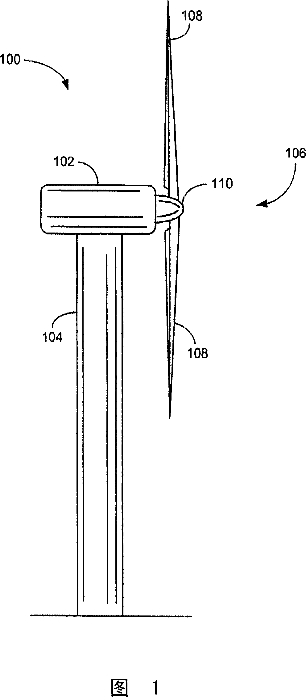
[0018] FIG. 1 is a diagram of an embodiment of a wind turbine 100 including a nacelle 102 , a tower 104 , a rotor 106 having at least one rotor blade 108 and a rotating hub 110 . A nacelle 102 is mounted atop a tower 104 , a portion of which is shown in FIG. 1 . Rotor blades 108 are connected to hub 110 .
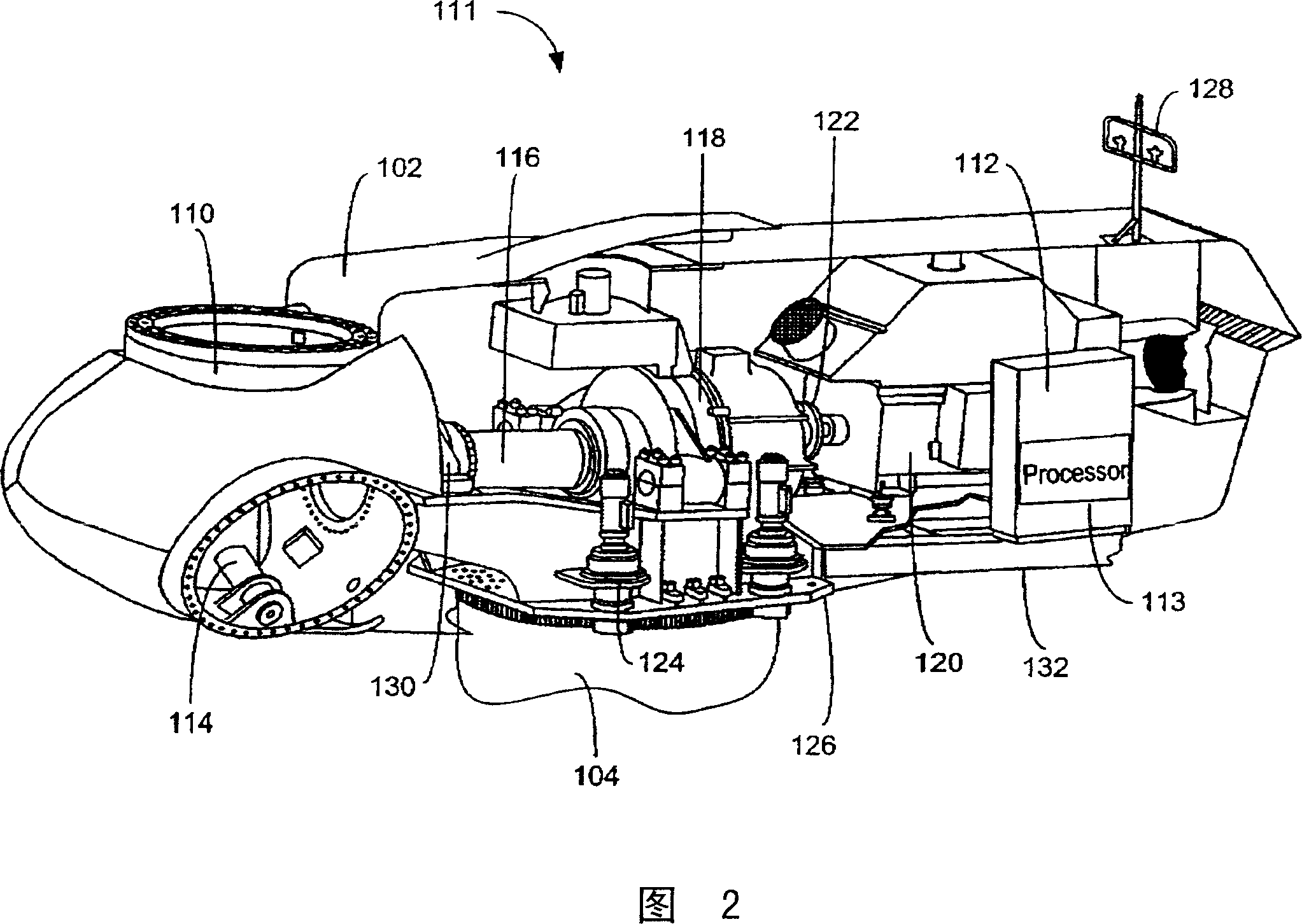
[0019] FIG. 2 is a diagram of an embodiment of a system 111 including nacelle 102 , tower 104 , and hub 110 . Nacelle 102 houses a control board 112 including a processor 113 . As used herein, the term processor is not limited to those integrated circuits referred to as processors in the prior art, but broadly refers to controllers, microcontrollers, microcomputers, programmable logic controllers, application-specific integrated circuit and any other programmable circuit.
[0020] The hub 110 contains a variable blade pitch drive 114 . Nacelle 102 also houses a portion of main rotor shaft 116 , gearbox 118 , generator 120 , and coupling 122 . Yaw drive 124 and yaw plat...
PUM
 Abstract
Description
Claims
Application Information