Electromagnetically driven valve
A technology of electromagnetic drive and drive valve, which is applied in the direction of electromagnet, non-mechanical actuated valve, electromagnet with armature, etc. It can solve the problem of increasing the sliding resistance of the valve stem, the inability of the driven valve to reciprocate smoothly, and displacement, etc. problem, to achieve the effect of smooth reciprocating motion
- Summary
- Abstract
- Description
- Claims
- Application Information
AI Technical Summary
Problems solved by technology
Method used
Image
Examples
no. 1 example
[0025] The electromagnetically driven valve according to the present embodiment constitutes an engine valve (intake valve or exhaust valve) in an internal combustion engine such as a gasoline engine or a diesel engine. In the present embodiment, description is made on the assumption that the electromagnetically driven valve is configured as an intake valve, however, note that when the electromagnetically driven valve is configured as an exhaust valve, the structure is similar.
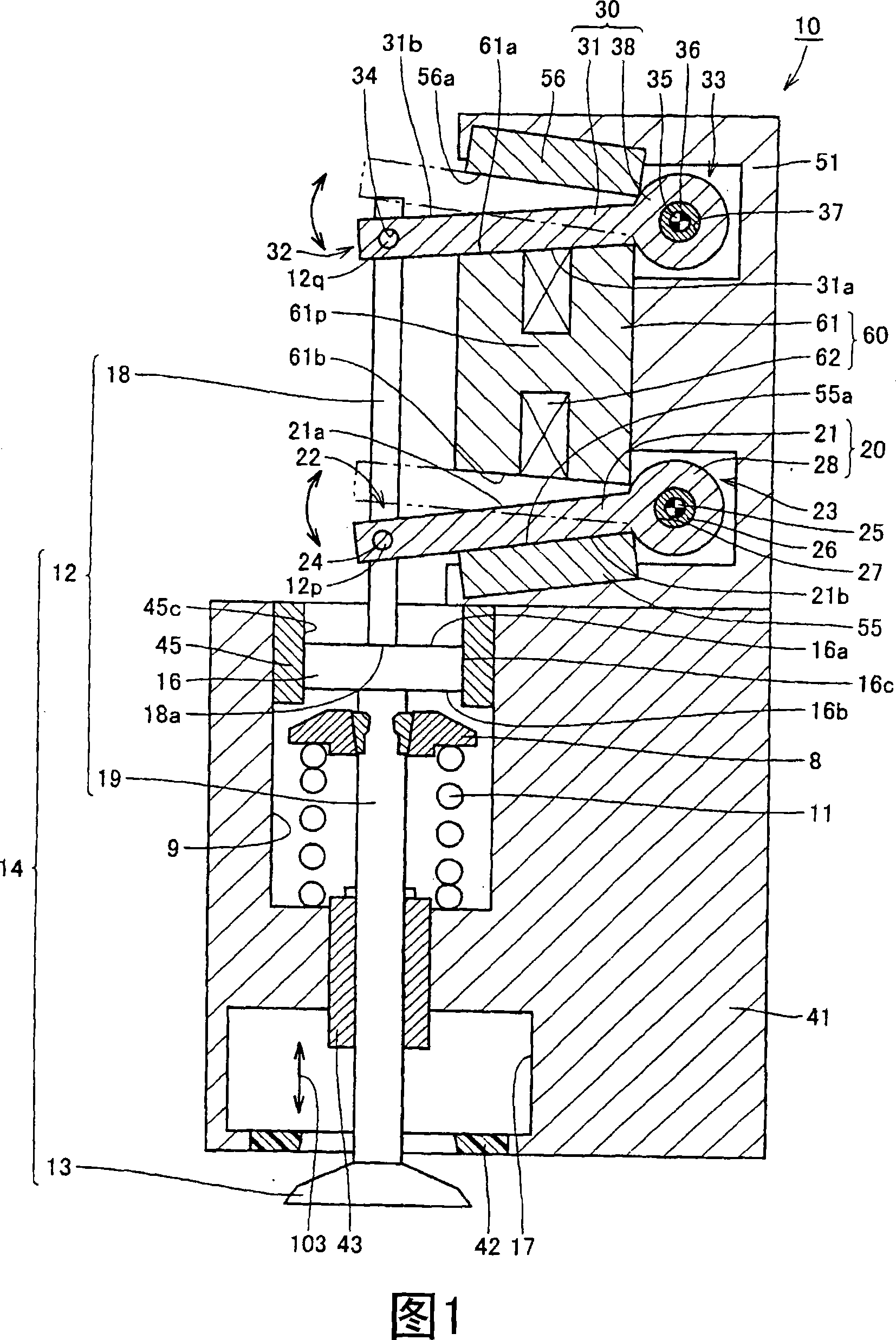
[0026] Referring to FIG. 1 , the electromagnetically driven valve 10 is a rotationally driven electromagnetically driven valve. The parallel linkage mechanism is used as the operating mechanism of the electromagnetically driven valve.
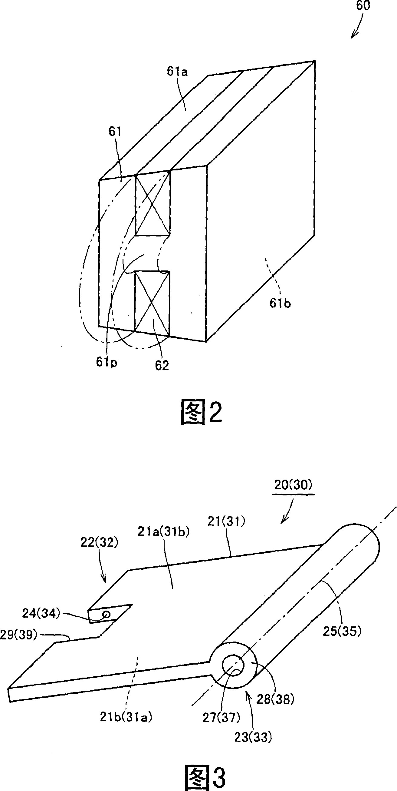
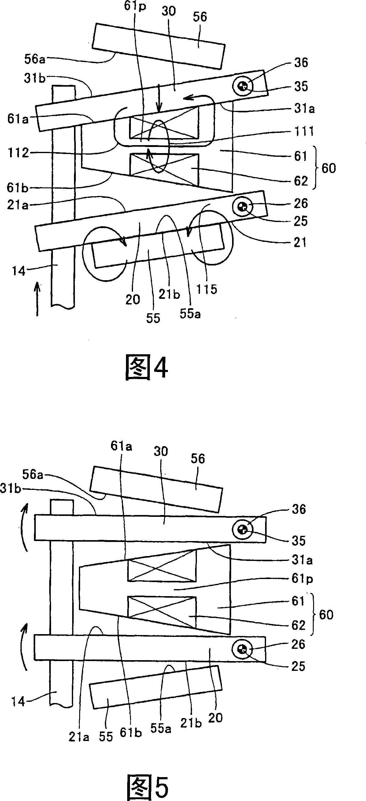
[0027] The electromagnetically driven valve 10 includes a driven valve 14 and a lower valve plate 20 and an upper valve plate 30, the driven valve 14 has a valve stem 12 extending in one direction and an umbrella portion 13 formed at the end of the valve stem 12, the lo...
no. 2 example
[0062] The electromagnetically driven valve according to the present embodiment is constituted substantially similarly to the electromagnetically driven valve in the first embodiment. Therefore, descriptions of redundant structures will not be repeated.
[0063] Fig. 9 is an enlarged view of a region where a lash adjuster is provided in the electromagnetically driven valve. Referring to FIG. 9 , an end surface 19 a is defined at a position where the lower stem 19 is connected to the bottom surface of the lash adjuster 16 . In this embodiment, the end of the upper stem 18 is shaped like a flange so that the area of the end face 18a is larger than the area of the end face 19a.
[0064] According to the electromagnetically driven valve in the second embodiment of the present invention constructed as above, effects similar to those of the first embodiment can be obtained. In addition, the contact area between the end surface 18a and the top surface 16a is reduced, enabling s...
no. 3 example
[0066] The electromagnetically driven valve according to the present embodiment is constructed substantially similarly to the electromagnetically driven valve in the first embodiment. Therefore, redundant description will not be repeated.
[0067] Fig. 10 is an enlarged view of a region where a lash adjuster is provided in an electromagnetically driven valve. Referring to FIG. 10 , the gap adjuster 16 is composed of an upper cover 81 having a top surface 16a, a lower cover 83 arranged at a predetermined distance from the upper cover 81 and having a bottom surface 16b, and a viscous material that fills the gap between the upper cover 81 and the lower cover 83. components 82 such as grease and oil. In this embodiment, the lower retaining ring 8 in FIG. 1 is not arranged in the lower valve stem 19 . The lower spring 11 is accommodated in the hollow portion 9 between the bottom surface of the hollow portion 9 and the lower cover 83 .
[0068] In the electromagnetically driven v...
PUM
 Abstract
Description
Claims
Application Information
 - R&D
- Intellectual Property
- Life Sciences
- Materials
- Tech Scout
- Unparalleled Data Quality
- Higher Quality Content
- 60% Fewer Hallucinations
Browse by: Latest US Patents, China's latest patents, Technical Efficacy Thesaurus, Application Domain, Technology Topic, Popular Technical Reports.
© 2025 PatSnap. All rights reserved.Legal|Privacy policy|Modern Slavery Act Transparency Statement|Sitemap|About US| Contact US: help@patsnap.com


