Secondary battery employing battery case of high strength

A secondary battery, battery case technology, applied in secondary batteries, battery pack components, battery boxes/jackets, etc., can solve problems such as explosion, intrusion, and easy damage

Active Publication Date: 2007-08-01
LG ENERGY SOLUTION LTD
View PDF0 Cites 4 Cited by
  • Summary
  • Abstract
  • Description
  • Claims
  • Application Information

AI Technical Summary

Problems solved by technology

[0007] However, conventional cases and covers made of an ONy outer coating, an aluminum (Al) barrier layer, and a CPP inner sealing layer have problems when batteries made of such cases and covers are exposed to physical shock or When squeezed by a pointed object, due to its fragility, such as intrusion, fire or explosion

Method used


Image

  • Secondary battery employing battery case of high strength
  • Secondary battery employing battery case of high strength

Examples


Embodiment 1-4 and comparative example 1

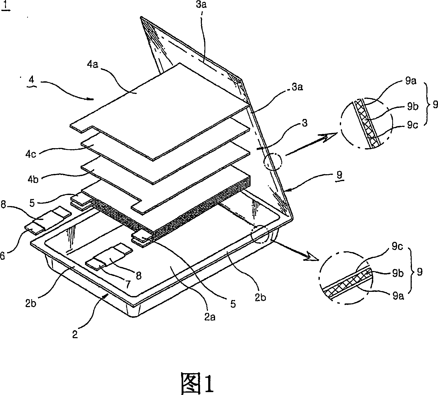
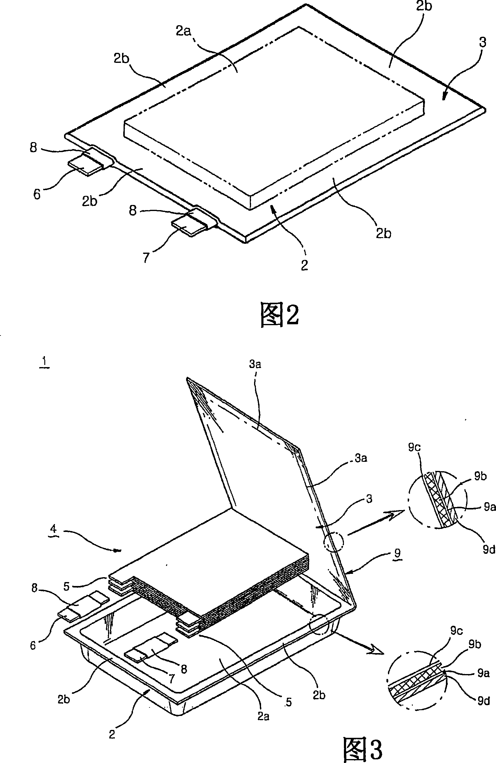
[0037] Laminates were prepared according to the synthesis formula in Table 2 below. Using the laminated sheet thus produced, a pouch-type battery case having a structure as shown in FIG. 3 was prepared by dry lamination.

[0038]

[0039] Structure of the laminate

[0040] Note: The right suffix for PET, ONy, PEN, Al and CPP indicates the thickness.

[0041] A laminated type electrode assembly, as shown in FIG. 3, is installed in each battery case, and the resulting structure is filled with electrolyte. Then, the case and the cover were heat-sealed therebetween, thereby producing a pouch-type battery.

[0042] The puncture resistance of the thus-prepared batteries was tested under the conditions of FTMS 101C using a battery puncture tester (UTM tester). The results obtained are given in Table 3 below. The puncture resistance strength of the above-described device is represented by the force measured when the needle-like member penetrates the battery case by pu...


PUM

PropertyMeasurementUnit
strengthaaaaaaaaaa
strengthaaaaaaaaaa
thicknessaaaaaaaaaa

Abstract

Provided is a secondary battery having an electrode assembly installed in a battery case made up of a laminated sheet composed of an outer coating layer of a polymer film, a barrier layer of a metal foil and an inner sealant layer of a polyolefin material, wherein the metal foil of the barrier layer is formed of an aluminum alloy, the outer coating layer is formed of polyethylene naphthalate (PEN) and / or the outer surface of the outer coating layer is provided with a polyethylene naphthalate (PET) layer, and wherein the battery has a nail penetration resistance force of more than 6.5 kgf. The battery in accordance with the present invention exhibits further improved safety due to the ability to significantly reduce the probability of invasion, ignition or explosion as compared to conventional batteries, even when the battery is exposed to external physical impact or is pressed by sharp objects.

Description

technical field [0001] The present invention relates to a secondary battery having a high-strength battery case. More specifically, the present invention relates to a secondary battery utilizing a high-strength battery case that significantly reduces intrusion, Fire or explosion hazard. Background technique [0002] Generally, a lithium ion polymer battery 1, also called a "pouch battery", as shown in FIGS. to the cover 3 of the case 2; the electrode assembly 4 including the cathode plate 4a, the anode plate 4b and the diaphragm sheet 4c, which is placed in the receiving portion 2a of the case 2; from the cathode plate 4a and the anode plate 4b of the electrode assembly 4 connection portions 5 whose ends extend outward in the lengthwise direction; and cathode terminals 6 and anode terminals 7 connected to the corresponding connection portions 5 . [0003] The extension portion 2 b has a predetermined width for heat sealing, and is formed horizontally and outwardly on the ...

Claims


Application Information

Patent Timeline
Patent Type & Authority Applications(China)
IPC IPC(8): H01M2/10H01M10/05H01M50/119H01M50/121H01M50/129H01M50/131H01M50/133H01M50/14
CPCH01M2/0285Y02E60/122H01M2/0277H01M2/0257H01M2/0287H01M10/0525H01M2002/0297H01M2/0292H01M50/131H01M50/124H01M50/1245H01M50/133H01M50/121H01M50/14H01M50/129H01M50/119H01M50/105Y02E60/10
Inventor 黄成敏洪起哲李香穆安昶范姜景元孙正三
Owner LG ENERGY SOLUTION LTD
Why Eureka
Try Eureka