Zip head moving device for zip assembly line

A mobile device and assembly line technology, applied in the direction of application, sliding fastener components, fasteners, etc., can solve problems such as increased cost, poor cutting, poor upper stop structure, etc., and achieve the effect of saving labor costs

Inactive Publication Date: 2007-08-08
SHANGHAI EASTDRAGON FABRIC & GARMENT
View PDF0 Cites 24 Cited by
  • Summary
  • Abstract
  • Description
  • Claims
  • Application Information

AI Technical Summary

Problems solved by technology

[0003] At present, in the automatic assembly line of zipper production, the position of the slider on each zipper on the long zipper tape to be cut is mostly determined by the zipper threading machine when the slider is assembled. Generally speaking, the slider is installed on the zipper The position of the stop structure is about 10cm. If the slider is at this position and the long zipper tape is cut off, since the zipper slider is not closed, an O-shaped opening will inevitably be formed between the top stop of the zipper, the slider, and the left and right zipper teeth. The cutting position on the left and right half of the zipper tape is not even when cutting
To prevent this phenomenon, it is necessary to manually push the slider to the vicinity of the upper stop, so as to facilitate the production of the cutting process, resulting in a lot of labor costs; due to the human push and pull of the head, it will cause the difference in the position of the slider, resulting in a certain ratio Cut off bad products
[0004] At present, the solution adopted by some manufacturers is to install a mechanical device on the cutting machine, and use the pull of the zipper to passively move the slider to the top of the top stop structure of the zipper, but this creates a new defect: that is, it cannot be directly inspected to the top stop. For the problem of poor structure, the inspector must move the slider down to check the quality of the appearance of the top stop, and the cost of inspection will increase
Furthermore, some zipper sliders are connected with longer pull tabs, and when the slider is passively moved to the top end of the top stop, the pull tabs will be cut off together when cutting, resulting in defective

Method used


Image

  • Zip head moving device for zip assembly line
  • Zip head moving device for zip assembly line

Examples


Embodiment Construction

[0017] The present invention will be further described in detail below in conjunction with the accompanying drawings and specific embodiments.

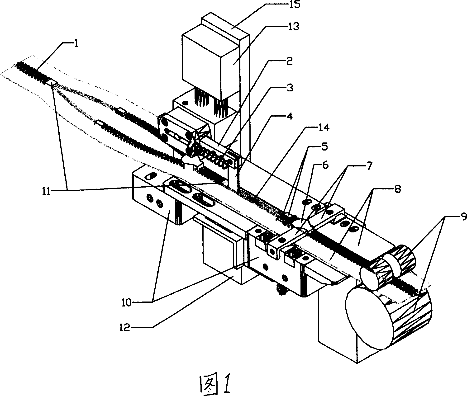
[0018] As shown in Figure 1, the base 10 is fixedly connected to the chain guide plate 8, the pulley 9 is connected to the rear end of the chain guide plate 8, and the left and right stoppers 7 of the slider that can rotate at a certain angle are set on the chain guide plate 8. The left and right setting directions of the left and right stoppers 7 are perpendicular to the chain guide plate 8, that is, perpendicular to the processing direction of the uncut zipper tape 1. The slider 6 can be caught and the zipper tape 1 can be passed through, and the slider 6 can be passed after turning. The rear end of the chain guide plate 8 is provided with a pulling pulley 9 for controlling the movement of the zipper belt 1 at a constant speed.

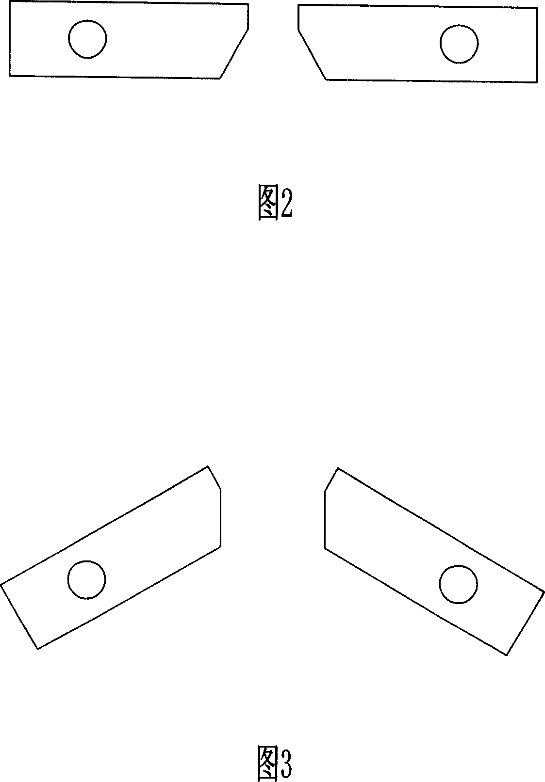
[0019] As shown in FIG. 2 , it is a schematic diagram when the left and right stoppers 7 of the slider ...


PUM


Abstract

The invention relates to an auxiliary device used in zip product line, especially relates to a zip moving device for moving the zip head to preset position, while said position can be controlled by the zip low-stop structure of next zip unit. The invention arranges a rotational zip head left and right blocks whose distance can clamp the zip head in return, and pass the zip head after rotation; the return and rotation of left and right blocks can be controlled by the sensitive signals generated by the movements that the zip head and low-stop structure at relative position. The invention can move the zip head to preset position before cutting and in the movement, to avoid hand operation.

Description

technical field [0001] The invention relates to an auxiliary device for a zipper production line, in particular to a slider moving device for a zipper assembly line that can move a slider to a preset position. Background technique [0002] The cutting process in zipper production is to cut the long zipper tapes with multiple zipper units and sliders, pull tabs, top stop and bottom stop structures that have been produced and processed into separate products. [0003] At present, in the automatic assembly line of zipper production, the position of the slider on each zipper on the long zipper tape to be cut is mostly determined by the zipper threading machine when the slider is assembled. Generally speaking, the slider is installed on the zipper The position of the stop structure is about 10cm. If the slider is at this position and the long zipper tape is cut off, since the zipper slider is not closed, an O-shaped opening will inevitably be formed between the top stop of the zi...

Claims


Application Information

Patent Timeline
Patent Type & Authority Applications(China)
IPC IPC(8): A44B19/42
Inventor 唐志强夏传峰
Owner SHANGHAI EASTDRAGON FABRIC & GARMENT
Why Eureka
Try Eureka