Novel cutter-exchange mechanism for manipulator

A tool changing mechanism and manipulator technology, applied in metal processing mechanical parts, clamping, support and other directions, can solve the problems of unsatisfactory tool change reliability, large manipulator swing angle, low work efficiency, etc. The effect of fast knife speed and small swing angle

Inactive Publication Date: 2007-08-08
NANTONG MACHINE TOOLS GROUP
View PDF0 Cites 15 Cited by
  • Summary
  • Abstract
  • Description
  • Claims
  • Application Information

AI Technical Summary

Problems solved by technology

[0002] The existing manipulator tool magazine has a large manipulator swing angle, slow tool change speed, low work efficiency, and unsatisfactory tool change reliability

Method used


Image

  • Novel cutter-exchange mechanism for manipulator

Examples


Embodiment Construction

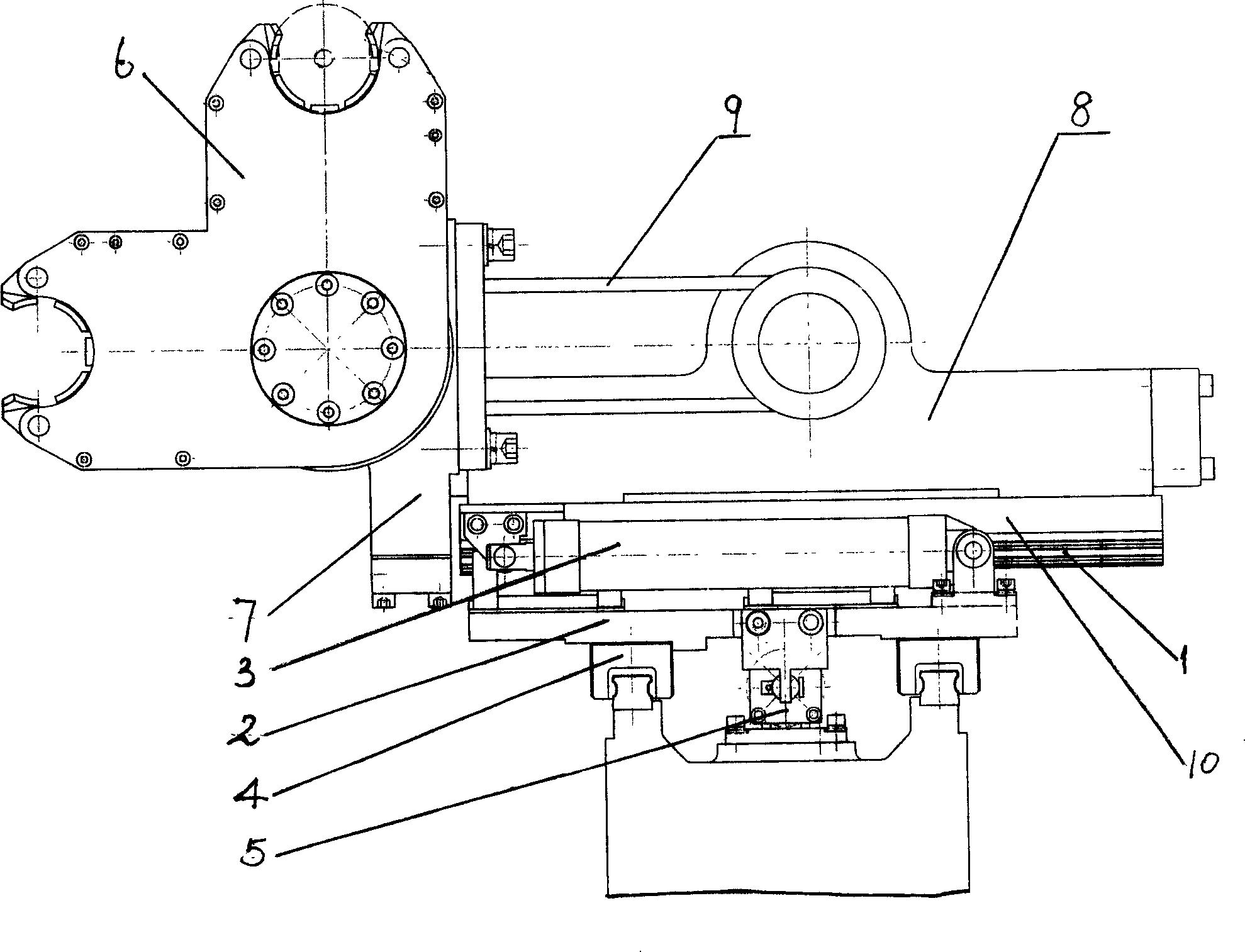
[0009] A new manipulator tool changing mechanism, including a manipulator swing device, the manipulator swing device is installed on the X-axis linear guide rail pair 1 through the second slide seat 10, and is connected with the second oil cylinder 3 installed on the first slide seat 2, the second A sliding seat 2 is installed on the Y-axis linear guide rail pair 4, and is connected with the first oil cylinder 5; the manipulator swing device includes a manipulator 6, and the manipulator 6 is connected with the first swing cylinder 7 that can swing at 90°. The second swing cylinder 8 of 180 ° swing is connected. The swing arm 9 of the second swing cylinder 8 is also shown in the figure.

[0010] In this tool change mechanism, the manipulator moves along the Y-axis coordinates along the linear guide rail pair 4 under the drive of the first oil cylinder 5, so as to realize the movement of the manipulator to draw and install the tool to the tool magazine or the main shaft; Under ...


PUM


Abstract

A new robot knife changing mechanism comprises robot oscillating device installed on X axis linear sub guide through the second sledge and connected with the second oil cylinder of the first sledge that installs on the Y axis linear sub guide and connects with the first oil cylinder, with the robot oscillating device composed of the robot connected with the oscillating cylinder with 90 degree oscillation, and the robot can link with the second oscillating cylinder with 180 degree oscillation. It is small in oscillating angle, quick in knife changing speed, better in component machining process, with improved knife changing reliability.

Description

Technical field: [0001] The invention relates to a tool changing mechanism of a machine tool. Background technique: [0002] The existing manipulator tool magazine has a large swing angle of the manipulator, slow tool change speed, low work efficiency, and unsatisfactory tool change reliability. Invention content: [0003] The purpose of the present invention is to provide a new manipulator tool changing mechanism with reasonable structure, high tool changing efficiency and good reliability. [0004] Technical solution of the present invention is: [0005] A new manipulator tool changing mechanism, characterized by: including a manipulator swing device, the manipulator swing device is installed on the X-axis linear guide pair through the second slide seat, and connected with the second oil cylinder installed on the first slide seat, the second A sliding seat is installed on the Y-axis linear guide pair and connected with the first oil cylinder; the manipulator swing devi...

Claims


Application Information

Patent Timeline
Patent Type & Authority Applications(China)
IPC IPC(8): B23Q3/155
Inventor 甘青陈俊杨琪吴金泉盛亚英陈玉华陈玉祝莉平邓鹏宇吴静飞张越冒晓波董佩
Owner NANTONG MACHINE TOOLS GROUP
Why Eureka
Try Eureka