Impact tool

A technology of impact tools and tools, which is applied in the field of impact tools, can solve problems such as complex structures, component wear, and increased manufacturing costs, and achieve the effects of improving durability and stabilizing vibration reduction

Inactive Publication Date: 2007-08-08
KOKI HLDG CO LTD
View PDF1 Cites 8 Cited by
  • Summary
  • Abstract
  • Description
  • Claims
  • Application Information

AI Technical Summary

Problems solved by technology

[0015] However, in this configuration, the face pressure on the contact portion between the key member and the groove is so high that there is a problem that the parts are worn prematurely, and the structure is complicated to increase the manufacturing cost

Method used


Image

  • Impact tool
  • Impact tool
  • Impact tool

Examples


Embodiment Construction

[0036] Hereinafter, embodiments of the present invention are explained with reference to the drawings.

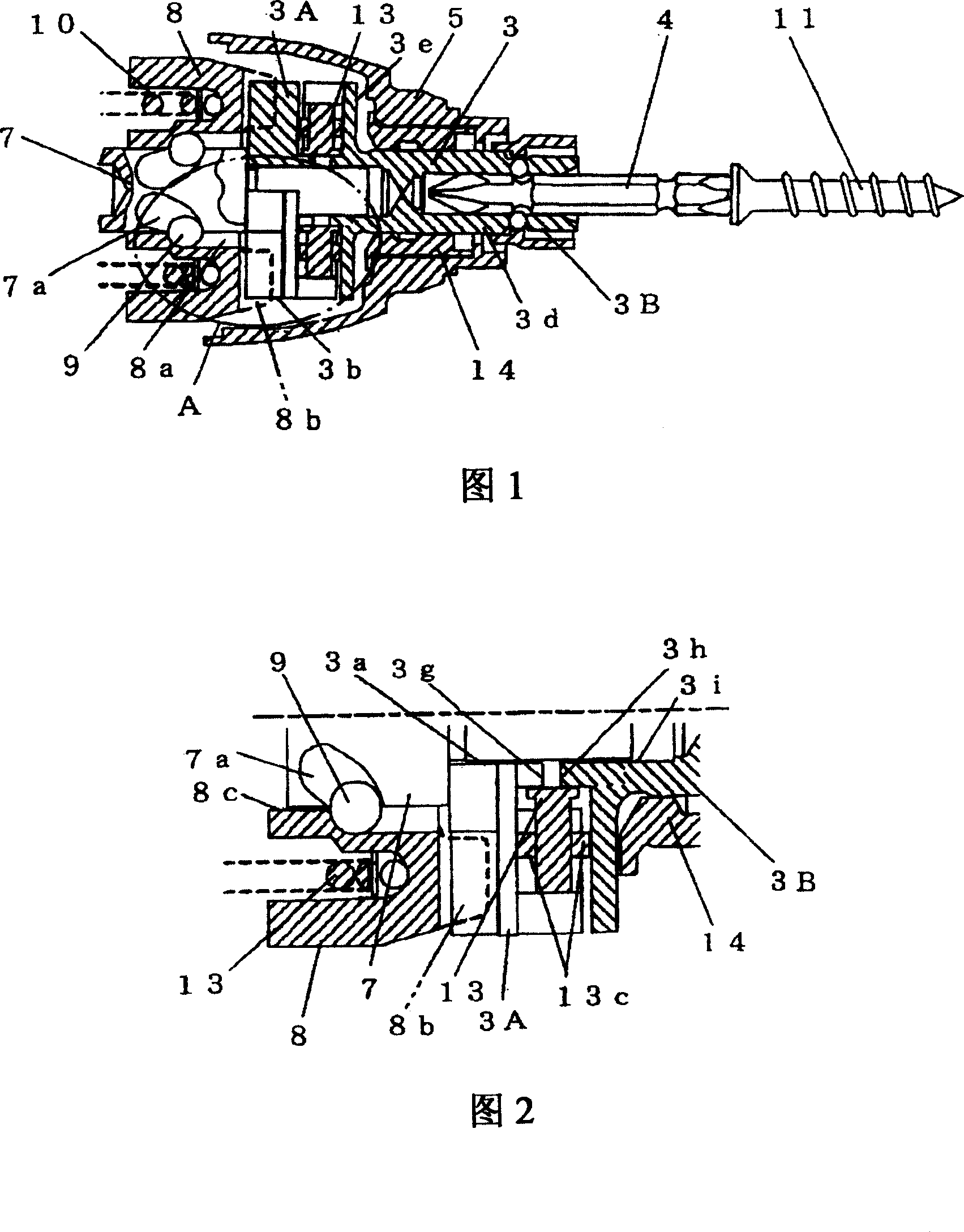
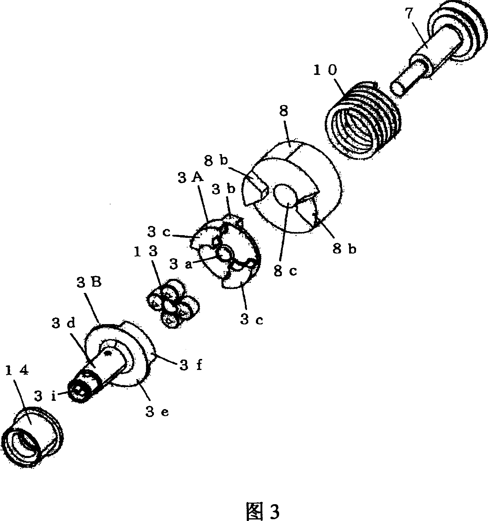
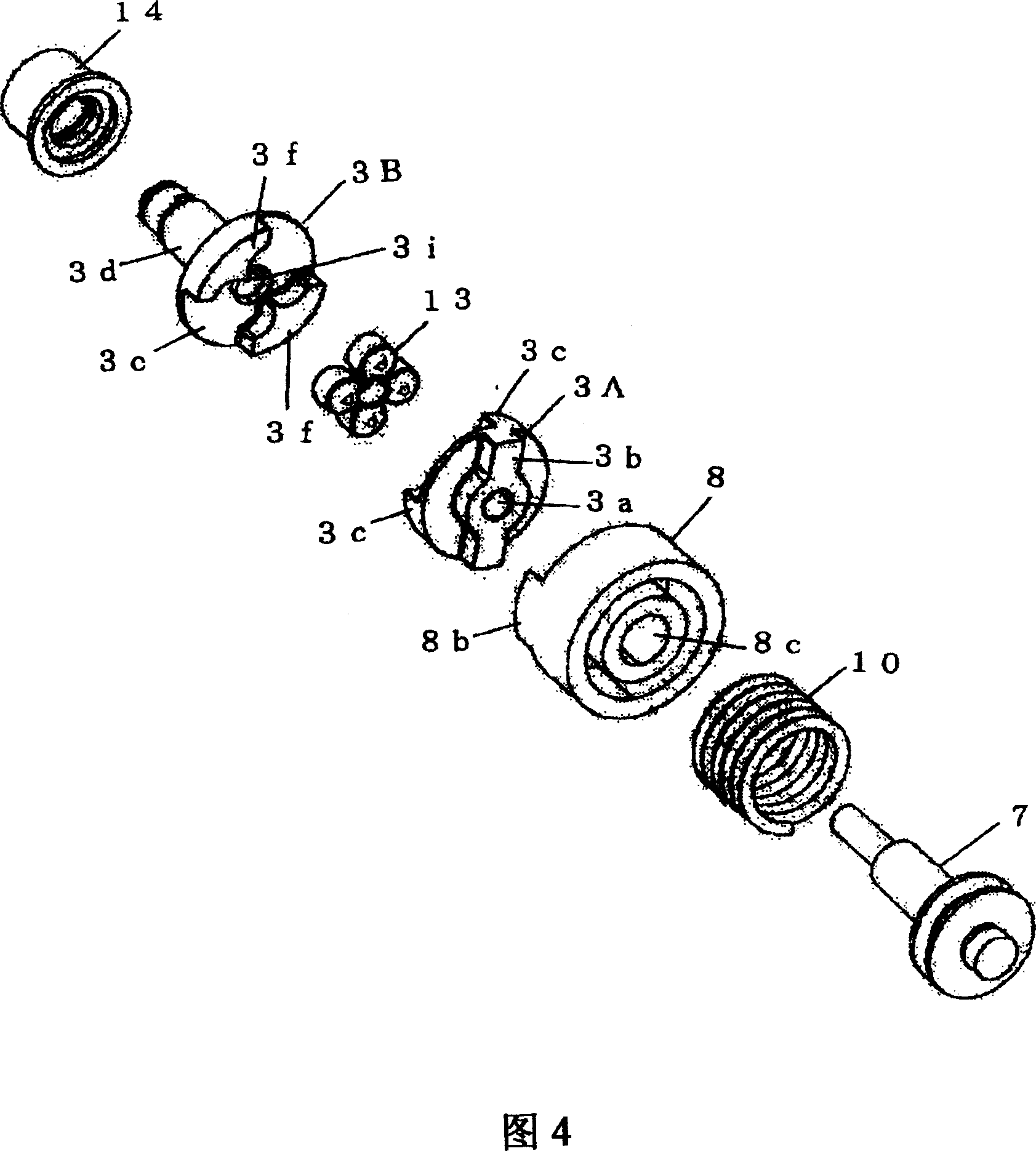
[0037] 1 is a longitudinal section of a rotary impact mechanism unit of an impact tool according to the invention. FIG. 2 is an enlarged detailed view of part A of FIG. 1 . 3 and 4 are exploded perspective views of the rotary impact mechanism unit of the impact tool. Fig. 5 is a side sectional view of an anvil of an impact tool. FIG. 6 is a cross-sectional view taken along line B-B of FIG. 5 . FIG. 7 is a cross-sectional view taken along line C-C of FIG. 6 . Fig. 8(a) is a front view of the rubber damper. Fig. 8(b) is a side view of the rubber damper. 9(a) and 9(b) are front views for explaining the operation of the pawl of the anvil. In these figures, the same components as those shown in FIG. 10 are denoted by the same reference numerals.

[0038]The impact tool according to the present embodiment is a cordless hand-held tool having a battery pack as a power source...


PUM


Abstract

An impact tool, which can realize the reduction of noise without inviting the reduction of a fastening ability and which can improve the durability of a damper while preventing its damage. The impact tool includes a rotary impact mechanism mounted on a spindle to be rotationally driven by a motor, so that rotary impact is applied to a tip tool by transmitting the rotary impact intermittently from a hammer through an anvil to the tip tool. A plurality of pawls are formed on two half members of the anvil in the axial direction. A rubber damper is disposed in a space between the pawls arranged alternately in the circumferential direction of the two half members. The minimum sectional area of the space formed between the pawls is set larger than the sectional area of the rubber damper.

Description

technical field [0001] The present invention relates to impact tools for generating rotational impact force to perform desired work such as screw fastening operations. Background technique [0002] An impact tool, which is one form of an electric tool, performs a tightening operation by generating a rotational impact force with a motor as a drive source, and rotating the tip tool by intermittently applying the impact force to the tip tool. Since the impact tool has advantages such as small reaction force and high fastening capacity, it is widely used at present. However, the impact tool has a rotary impact mechanism for generating a rotary impact force, which makes the impact tool noisy during operation, thereby causing noise problems. [0003] Fig. 10 is a longitudinal section showing a general impact tool used in the prior art. [0004] The prior art impact tool shown in FIG. 10 performs a tightening operation by driving a rotary impact mechanism unit using a battery pac...

Claims


Application Information

Patent Timeline
Patent Type & Authority Applications(China)
IPC IPC(8): B25D17/24B25D17/11B25D16/00B25B21/02
CPCB25B21/02B25B21/023
Inventor 村上卓宏上村淳一大森和博大津新喜稻川裕人
Owner KOKI HLDG CO LTD
Why Eureka
Try Eureka