Hybrid-drive vehicle

A hybrid vehicle and hybrid operation technology, applied in the direction of hybrid vehicles, motor vehicles, power plants, etc., can solve problems such as weakened efficiency

Inactive Publication Date: 2007-08-08
FAB ITAL MAGNETI MARELLI SPA
View PDF2 Cites 18 Cited by
  • Summary
  • Abstract
  • Description
  • Claims
  • Application Information

AI Technical Summary

Problems solved by technology

On the other hand, at certain operating points, the efficiency of hybrid vehicles in "series" mode is impaired due to the dual energy conversion from mechanical to electric and from electric to mechanical

Method used


Image

  • Hybrid-drive vehicle
  • Hybrid-drive vehicle

Examples


Embodiment Construction

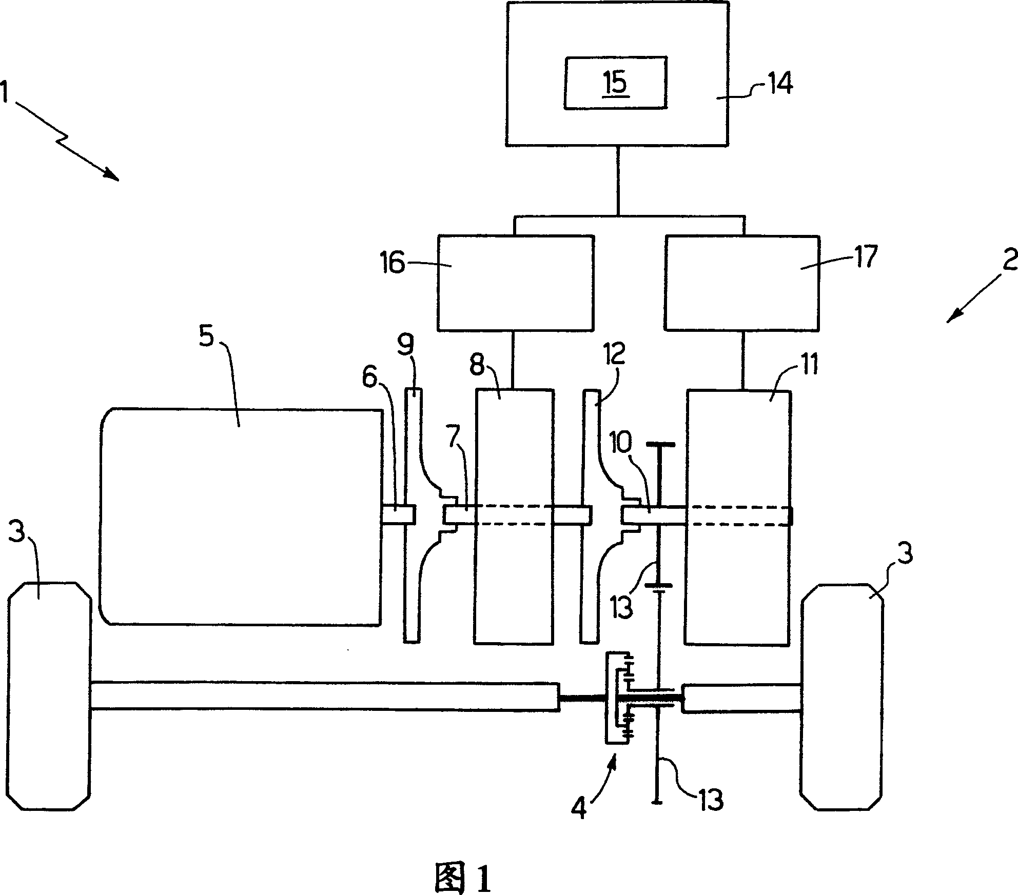
[0020] Numeral 1 in FIG. 1 designates a hybrid vehicle as a whole, which includes a transmission system 2 for applying drive torque to two drive wheels 3 via a differential 4 .

[0021] The transmission system 2 comprises a combustion engine 5 (in particular, an internal combustion engine or ICE) having a shaft 6 mechanically connected to the motor of a reversible electric motor generator (EMG) 8 via a decoupling system defined by a clutch (CL) 9 . Axis 7. Shaft 7 of reversible electric motor generator 8 is in turn mechanically connected to shaft 10 of reversible electric motor generator (EMG) 11 via a disconnect system defined by clutch 12 . In other words, the reversible electric motor generator 8 is located between the combustion generator 5 and the reversible electric motor generator 11 , one end of the shaft 7 of the reversible electric motor generator 8 is assembled on the clutch 9 , and the counter end is assembled on the clutch 12 .

[0022] The shaft 10 of the revers...


PUM


Abstract

A hybrid-drive vehicle (1) having a pair of drive wheels (3); a combustion engine (5) having a drive shaft (6); a first electric motor-generator (8) having a first shaft (7) connected mechanically to the drive shaft (6) of the combustion engine (5); a second electric motor-generator (11) having a second shaft (10); and an electric power supply device (14) connected electrically to the two electric motor-generators (8, 11) and having a storage device (15); the first shaft (7) of the first electric motor-generator (8) is connected at one end to the drive shaft (6) of the combustion engine (5), and is connected at the opposite end to the drive wheels (3) with a fixed, non-adjustable velocity ratio.

Description

technical field [0001] The present invention relates to hybrid-drive vehicles. Background technique [0002] A hybrid vehicle is a vehicle that has at least one combustion engine (usually an internal combustion engine) and at least one electric motor, and can usually be driven with only the electric motor (low performance and range, but zero pollutant emissions) and only with the combustion engine (high performance) and range), but with significant pollutant emissions), or both. [0003] Known hybrid vehicles operate in a "parallel" mode in which the internal combustion engine is mechanically connected to a reversible electric machine and to the drive wheels so as to transmit drive torque directly to the drive wheels. When the internal combustion engine transmits drive torque directly to the drive wheels, the reversible electric motor can be switched off and can be operated as a generator to charge a storage device, or can be operated (for short periods of time) as a motor ...

Claims


Application Information

Patent Timeline
Patent Type & Authority Applications(China)
IPC IPC(8): B60K6/04B60K6/442B60L50/16
CPCY02T10/6234B60K5/04B60K6/442Y02T10/62
Inventor 马西莫·塞米纳拉马尔科·拉伊莫尼
Owner FAB ITAL MAGNETI MARELLI SPA
Why Eureka
Try Eureka