
System component for a knitting system, and handling process

A technology of knitting system and components, which is applied in weft knitting, warp knitting, textiles and papermaking, etc., and can solve the problems of not setting auxiliary tools for knitting needles

Active Publication Date: 2007-08-08
GROZ BECKERT KG
View PDF5 Cites 2 Cited by
  • Summary
  • Abstract
  • Description
  • Claims
  • Application Information

AI Technical Summary

Problems solved by technology

However, no specific aids are provided for transferring the needles from the cylinder to the delivery package

Method used


Image

  • System component for a knitting system, and handling process
  • System component for a knitting system, and handling process
  • System component for a knitting system, and handling process

Examples


Embodiment Construction

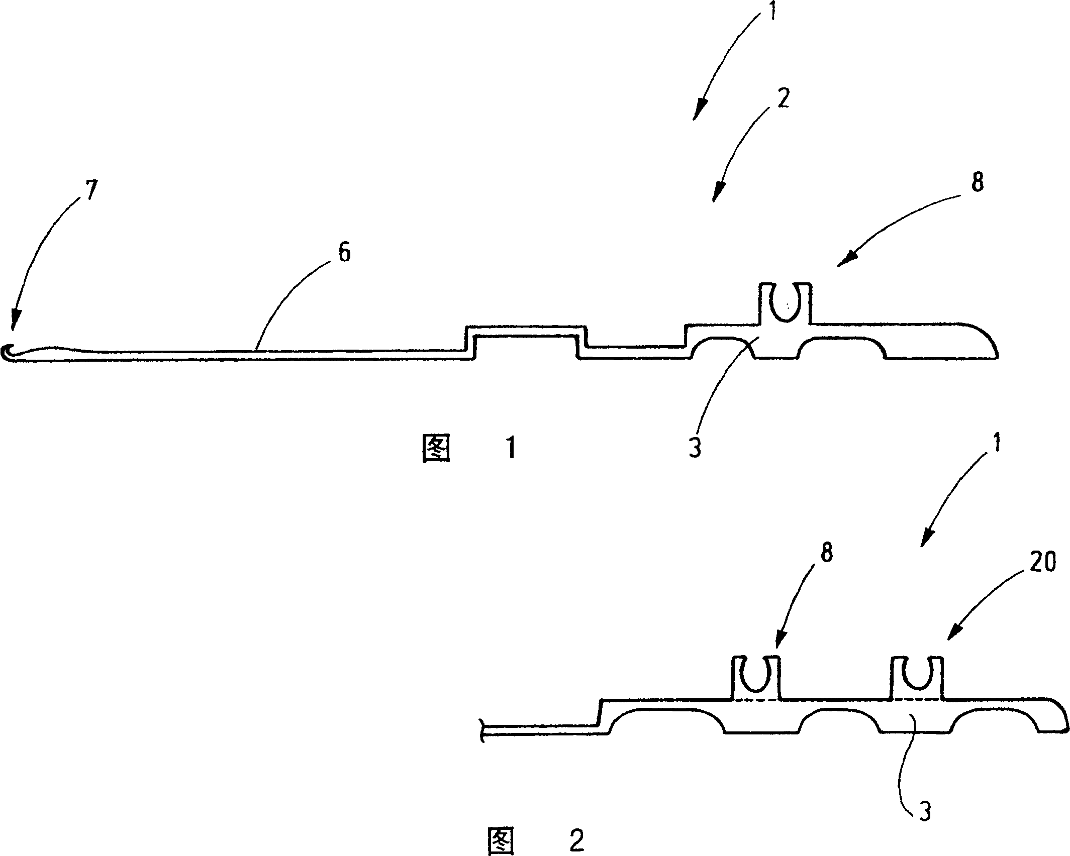
[0028] FIG. 1 shows as an example a system component 1 of a knitting machine using knitting machine needles 2 . The knitting machine needle 2 is for illustration only. The invention can also be implemented with other system components, eg sinkers, selection components or the like.

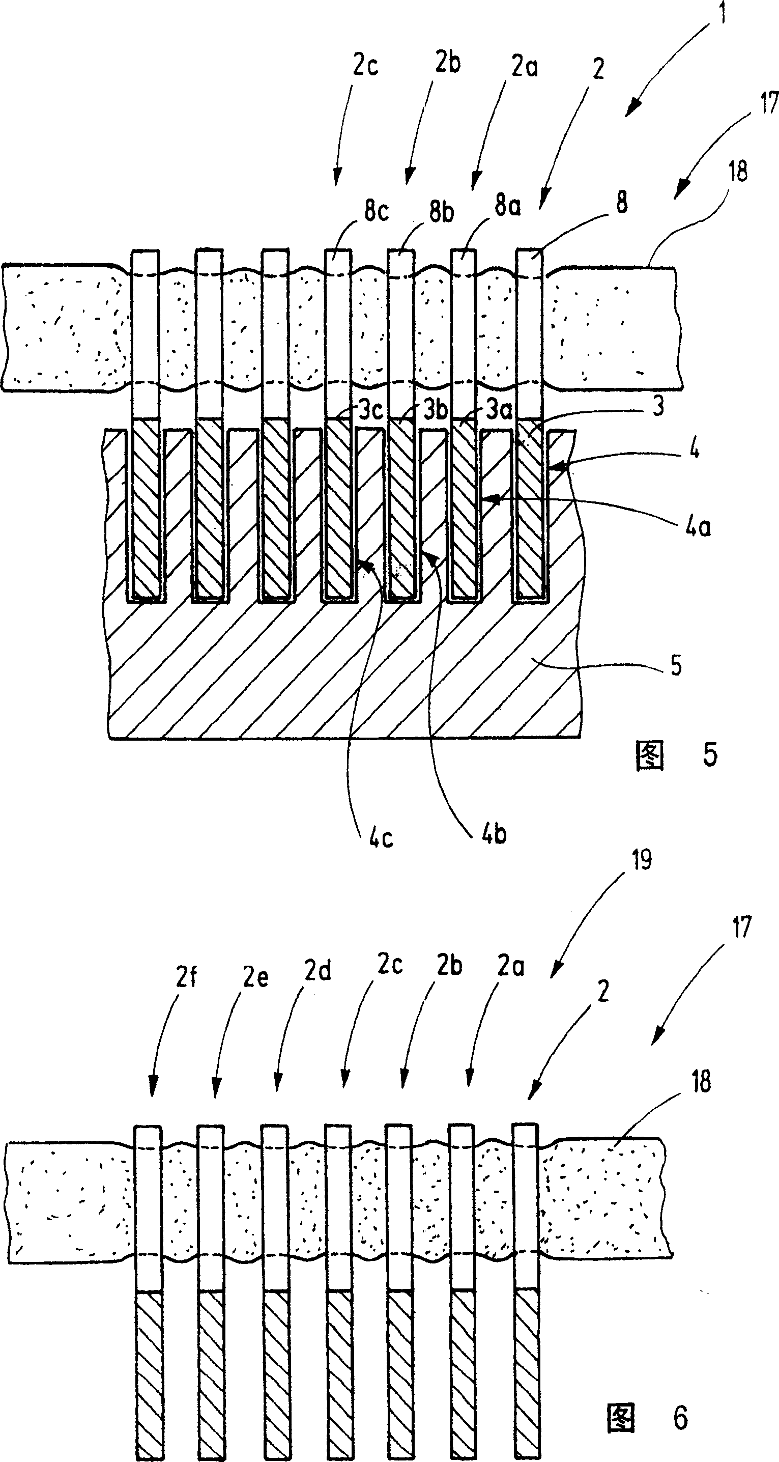
[0029] The knitting machine needle 2 has a body 3 which, as shown in FIG. 2 , is placed into a guide 4 of a needle bed 5 . The needle bed 5 is, for example, a flat bed of a flat knitting machine, a needle cylinder of a circular knitting machine or its dial. Said needle bed has a plurality of adjacent guide grooves 4, 4a, 4b, 4c, etc., wherein the bodies 3, 3a, 3b, 3c, etc. of the knitting machine needles 2, 2a, 2b, 2c, etc. are arranged in their longitudinal direction The way to be able to move is fixed.

[0030] The body 3 of the knitting machine needle 2 has a shaft 6 and on the end of said shaft a hook 7 or other functional part is provided. During operation, the knitting machine 2 performs ...


PUM


Abstract

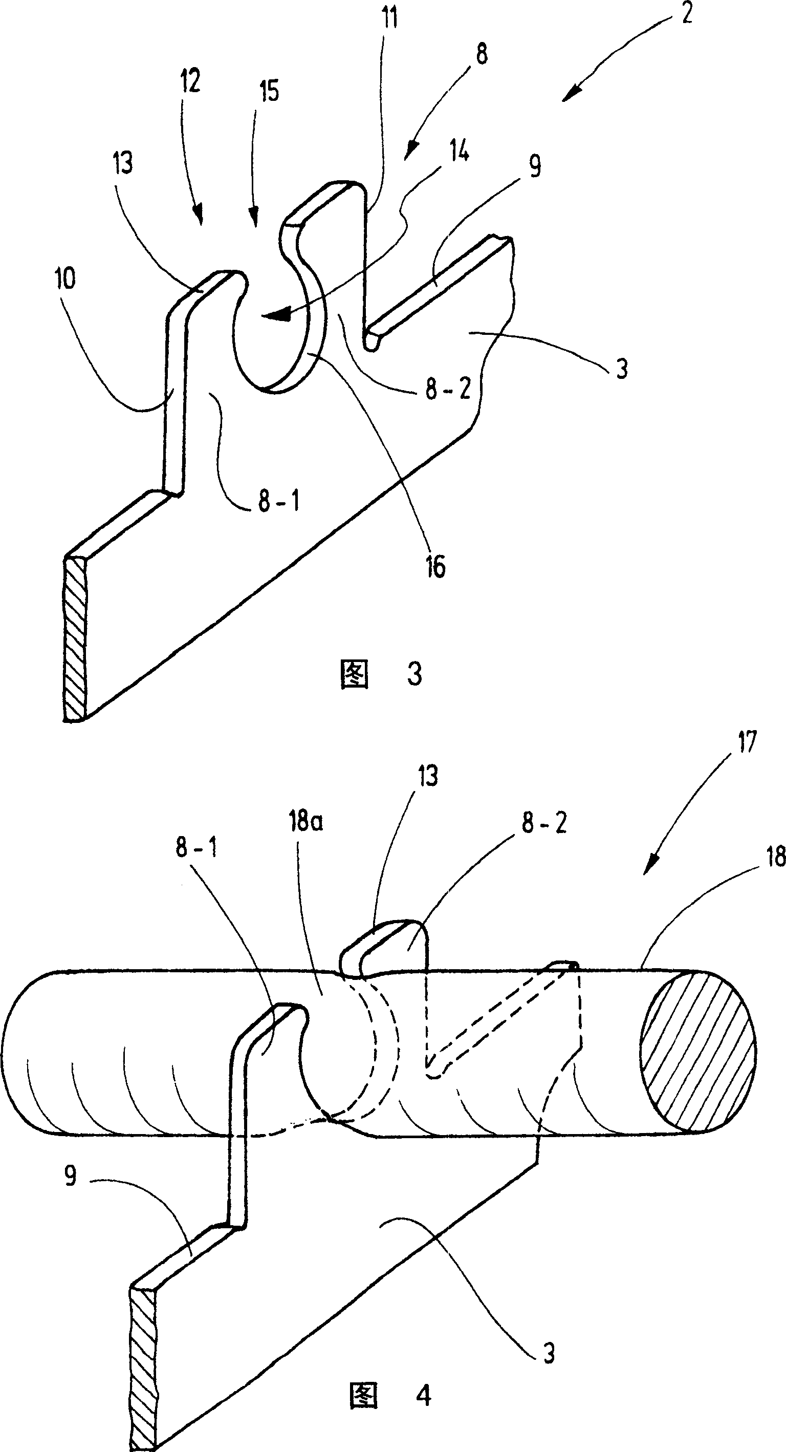
A system component ( 1 ), such as, for example a knitting machine needle ( 2 ), intended for a loop-forming machine has in its foot ( 8 ) at least one cutout ( 14 ) that is set up to accommodate a section of a holder ( 17 ). This holder can be clipped into the cutout in order to hold several such system components in a pre-specified sequence and at a lateral distance and in alignment with respect to each other. The systems components, which are thus temporarily connected to each other, can be handled as a unit and, in this manner, can be removed from the bed ( 5 ), can be treated, for example be cleaned, and can be replaced in the same sequence and alignment in the bed ( 5 ).

Description

technical field [0001] The invention relates to a system component for a knitting system, such as a knitting machine needle, a selection element, a sinker, a clutch element or the like. Background technique [0002] A large number of such systems are used in knitting machines, for example flat knitting machines or circular knitting machines. These machines have needle beds in which the guides for receiving the system components are arranged next to each other. For flat knitting machines, the guide grooves are arranged parallel to each other in a flat base. This is also true for the cylinders of circular knitting machines. The needle bed can also be designed as a dial of a knitting machine or as a sinker ring of a circular knitting machine. In this case, the channels are arranged radially so that adjacent channels together subtend an acute angle. [0003] In order to clean the needles and / or sinkers of a knitting machine, system components must be removed from the machine...

Claims


Application Information

Patent Timeline
IPC IPC(8): D04B15/00D04B15/06D04B15/32D04B27/00D04B27/04D04B35/00
CPCB65F1/062B65F1/16B65F2210/18B65F2220/116
Inventor U·斯丁格尔
Owner GROZ BECKERT KG
Learn More