Surface defect inspection apparatus, surface defect inspection method, and surface defect inspection program

A technology of defect inspection and camera device, which is applied in the direction of measuring device, optical device, optical test defect/defect, etc., which can solve the problem of increasing maintenance man-hours

Inactive Publication Date: 2007-08-08
RICOH KK
View PDF1 Cites 14 Cited by
  • Summary
  • Abstract
  • Description
  • Claims
  • Application Information

AI Technical Summary

Problems solved by technology

For this reason, there is a problem of increasing maintenance man-hours after the introduction

Method used


Image

  • Surface defect inspection apparatus, surface defect inspection method, and surface defect inspection program
  • Surface defect inspection apparatus, surface defect inspection method, and surface defect inspection program
  • Surface defect inspection apparatus, surface defect inspection method, and surface defect inspection program

Examples


no. 1 approach

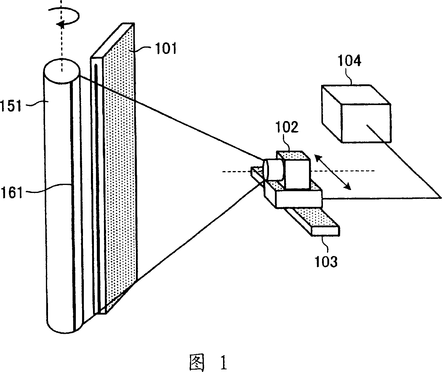
[0092] FIG. 1 is a perspective view showing the configuration of a surface defect inspection apparatus 100 according to the first embodiment. As shown in the figure, the surface defect inspection device 100 is composed of a line light source 101 , a line sensor 102 , a linear stand 103 , and a housing 104 , and inspects whether there is a defect on the surface of a rotating inspection object 151 .

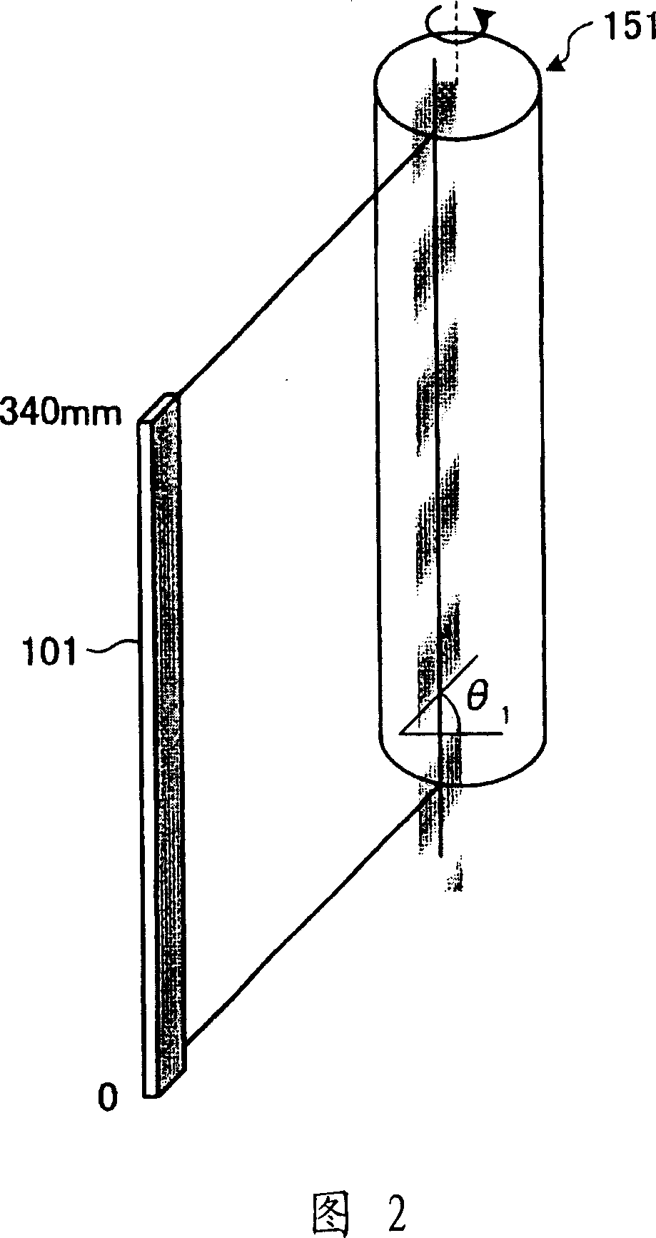
[0093] The inspection object 151 may have any shape, and in this embodiment, a cylindrical photoreceptor drum will be described as an example. The inspection object 151 is rotated, and the inspection position of the inspection object irradiated with pattern light from the line light source 101 described later moves with time. In this way, the line sensor 102 can inspect the entire surface of the inspection target object 151 .

[0094] The line light source 101 irradiates the rotating inspection object with long pattern light having a predetermined pattern in the longitudinal direc...

no. 2 approach

[0162] In the above-mentioned embodiment, the period of the luminance of the pattern light is ten times or more of the size of the defect to suppress the decrease in the detection accuracy of the defect, but it is not limited to such an embodiment. Here, in the second embodiment, a case where the pattern light is irradiated outside the defect detection area object will be described. The surface defect inspection device in the second embodiment has substantially the same configuration as that shown in FIG. 1 in the first embodiment, and only the different points will be described below.

[0163] FIG. 15 is an explanatory view showing a state in which a line light source 1301 according to the present embodiment irradiates pattern light on an object 151 to be inspected. As shown in the figure, the patterned light irradiated by the line light source 1301 irradiates the light without pattern in the detection area, and irradiates the patterned light in the area outside the detection...


PUM


Abstract

A surface-defect inspection apparatus includes a line light source that irradiates a pattern light having brightness differentiated in a direction oblique to a sub-scanning direction of a rotating inspection target object; a line sensor that carries out a one-dimensional imaging of the inspection target object in a main scanning direction using an irradiated pattern light and reflected from the inspection target object; a phase detecting unit that detects a change of the phase of the brightness of a taken line image; and an control unit that controls the position of the line sensor to keep constant a relative distance between a position of the inspection target object and a position of the line sensor from a change of the phase.

Description

technical field [0001] The present invention relates to a surface defect inspection device, a surface defect inspection method and a surface defect inspection program, in particular to a defect detection technology using a one-dimensional imaging device. Background technique [0002] Conventionally, uniform light is irradiated on the surface of an inspection object, the distribution of the reflected light is imaged, and flaws, unevenness, and dirt on the surface of the inspection object are detected from the captured image. [0003] In particular, when the object to be detected is a flat object such as a rolled paper or a thin plate, or a cylindrical object, a line sensor is generally used as an imaging device. The line sensor scans an object to be inspected that moves or rotates relative to the line sensor, obtains a surface image, and detects defects. [0004] When detecting defects in this way, the relative position between the light-receiving position of the reflected l...

Claims


Application Information

Patent Timeline
Patent Type & Authority Applications(China)
IPC IPC(8): G01N21/89
CPCG01N21/8806G01B11/2527G01N21/952G01N2021/1774G01N2021/8887G01N2201/0635
Inventor 鎌田照己
Owner RICOH KK
Why Eureka
Try Eureka