Lift conveyor

A conveyor, lift-type technology, applied in the direction of conveyor, conveyor objects, transportation and packaging, can solve the problems of occupying space, large structure, poor safety, etc., to ensure compactness, structure, and safety.

Inactive Publication Date: 2010-05-19
常熟市诚达港务机械设备厂
View PDF7 Cites 0 Cited by
  • Summary
  • Abstract
  • Description
  • Claims
  • Application Information

AI Technical Summary

Problems solved by technology

[0004] However, the conveyors currently used in the above-mentioned occasions have the following disadvantages during use: one is that the conveyor is always in the original position once it is installed, that is to say, it extends from the upper layer to the lower layer when it is not in use. Even the part extending to the floor is always kept in the normal use state and unreasonably occupies the space; the second is that the motor and reducer as the power transmission mechanism of the conveyor are split and exposed, which brings structural problems. The unfavorable factors of large size and poor safety; the third is that in the process of conveying goods (products), the goods are easy to fall outside the conveyor belt and cause damage, and there is also the unsafe hidden danger of goods hurting people

Method used


Image

  • Lift conveyor
  • Lift conveyor
  • Lift conveyor

Examples


Embodiment Construction

[0020] The applicant provides a more detailed description of the technical features and expected technical effects of the present invention with reference to the accompanying drawings. However, the description of all embodiments does not constitute a restriction on the technical solution of the present invention. Equivalent changes or formal or textual modifications of the technical content, especially the defined protection scope, shall be regarded as the scope covered by the patent.

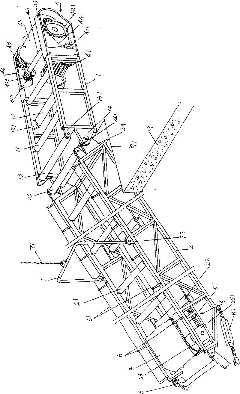
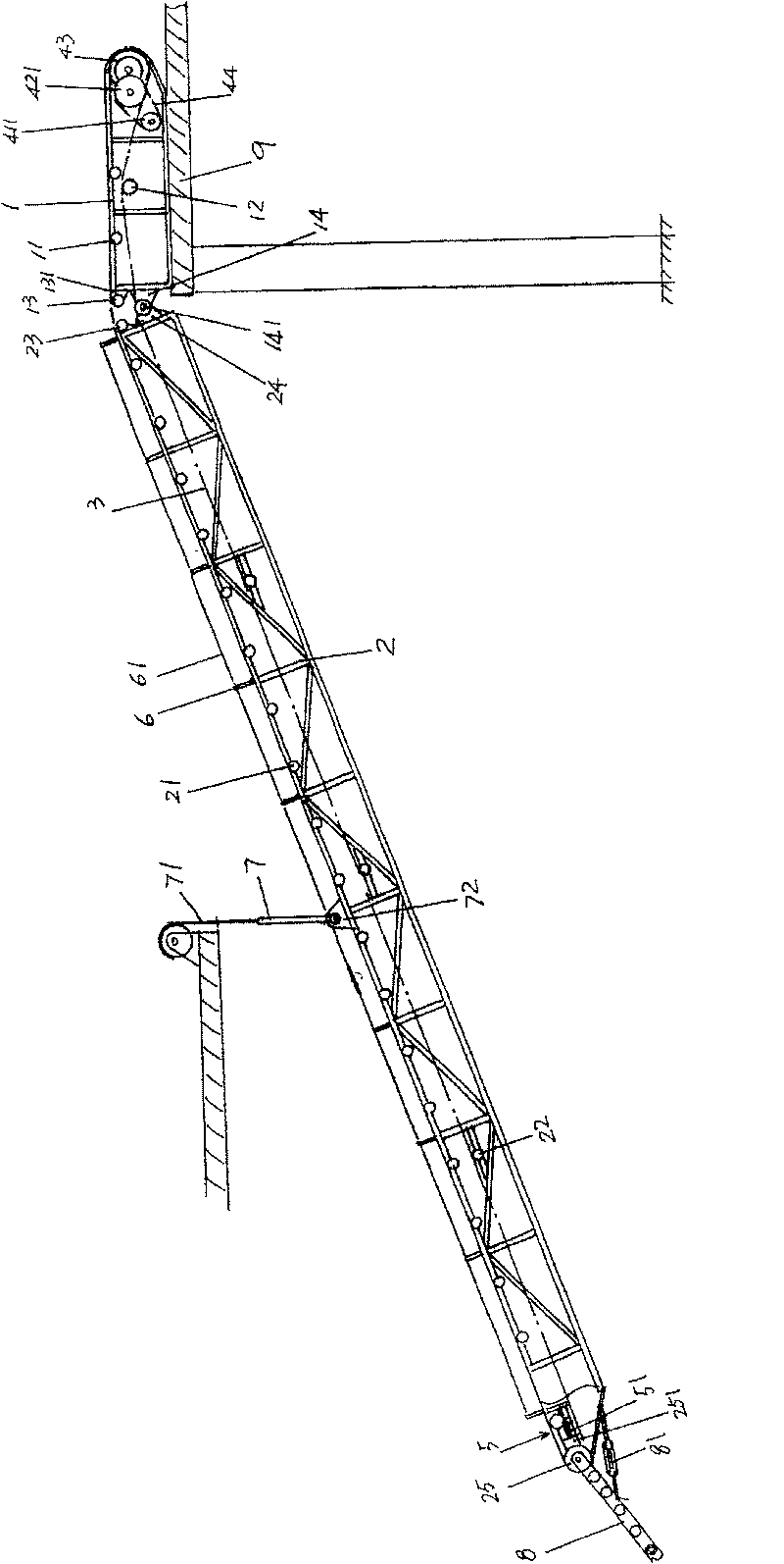
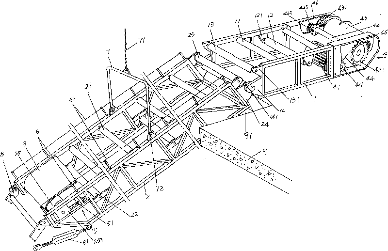
[0021] exist figure 1 In , the static frame 1 of the lifting conveyor is given. Usually, the static frame 1 is fixedly installed on the floor of the upper floor. In order to facilitate people's better understanding, the applicant also shows in the figure Out of the floor 9 of the floor, a cavity or gap is opened on the floor 9, and the applicant is commonly referred to as the opening 91. If the static frame 1 is fixed on the floor 91 of the fourth floor or the third floor or the second floor o...


PUM


Abstract

A lifting transmitter comprises a stable support fixed on upper floor, a movable support whose one end is connected with the stable support and another end extends to lower floor, a force gear on thestable support, and a transmission band connected with the force gear for moving around the movable and stable supports to form a transmission plane. The connection between the movable and stable supports is hinge connection, while the movable support is extended arranged with a movable support landing device. The invention can use the landing device to lift up the free movable support, to save space and shade all gears in the force gear. And the invention arranges bars on the movable support to protect the elements.

Description

technical field [0001] The invention relates to an elevating conveyor, which is suitable for conveying articles in warehousing, logistics industry, large supermarkets, factories, etc., and belongs to the technical field of operation transportation devices. Background technique [0002] In the industries mentioned above, special conveyors are often required to transfer packaged or packaged products from one place to another. For example, taking an industrial enterprise as an example, if the products on a certain floor are to be transported to the bottom floor for delivery (goods), etc., the traditional method is to invest a lot of human resources in handling. The disadvantage is that the labor intensity of the workers is high and the efficiency is low. Prolong the transit and delivery time of goods. [0003] In view of the above situation, there is a targeted conveyor, which is to open a cavity (also known as a gap) in a certain place in the warehouse or workshop or supermar...

Claims


Application Information

Patent Timeline
Patent Type & Authority Patents(China)
IPC IPC(8): B65G15/00B65G41/00B65G23/24B65G39/12B65G39/02B65G15/30B65G15/32
Inventor 奚卫平
Owner 常熟市诚达港务机械设备厂
Why Eureka
Try Eureka