Strip ribbon lap machine

A technology of sliver doubling machine and coiling machine, which is applied in the direction of coiling mechanism, spinning machine, textile and paper making, etc. It can solve the problems of large space occupied by the machine, repetitive and complicated mechanical structure, etc.

Inactive Publication Date: 2007-08-15
JIANGSU KAIGONG MACHINERY
View PDF1 Cites 1 Cited by
  • Summary
  • Abstract
  • Description
  • Claims
  • Application Information

AI Technical Summary

Problems solved by technology

The drafting mechanism is installed in multiple parts of a sliver doubling machine, which makes the machine occupy a large space, and the mechanical structure is repetitive and complicated

Method used


Image

  • Strip ribbon lap machine
  • Strip ribbon lap machine
  • Strip ribbon lap machine

Examples


Embodiment Construction

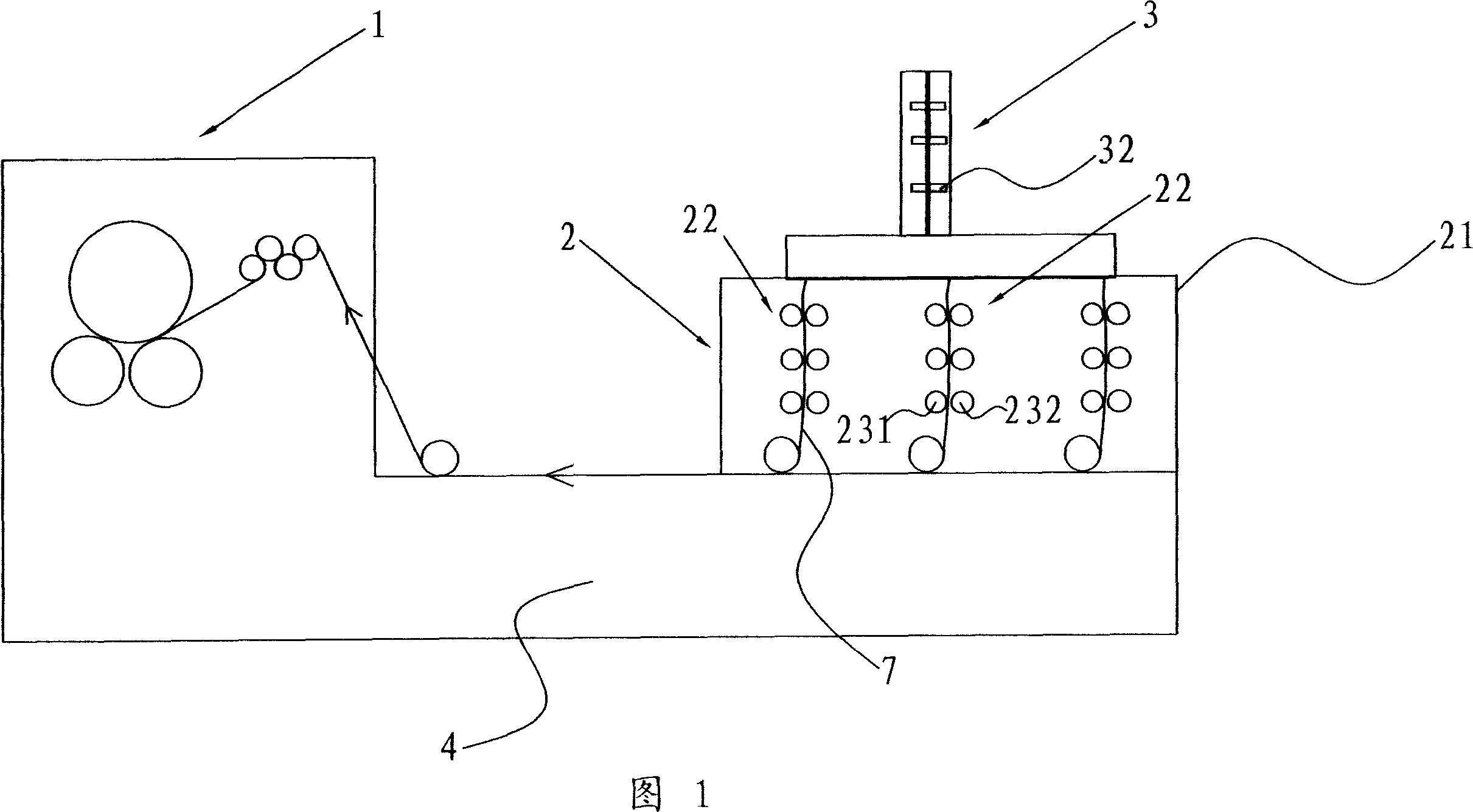
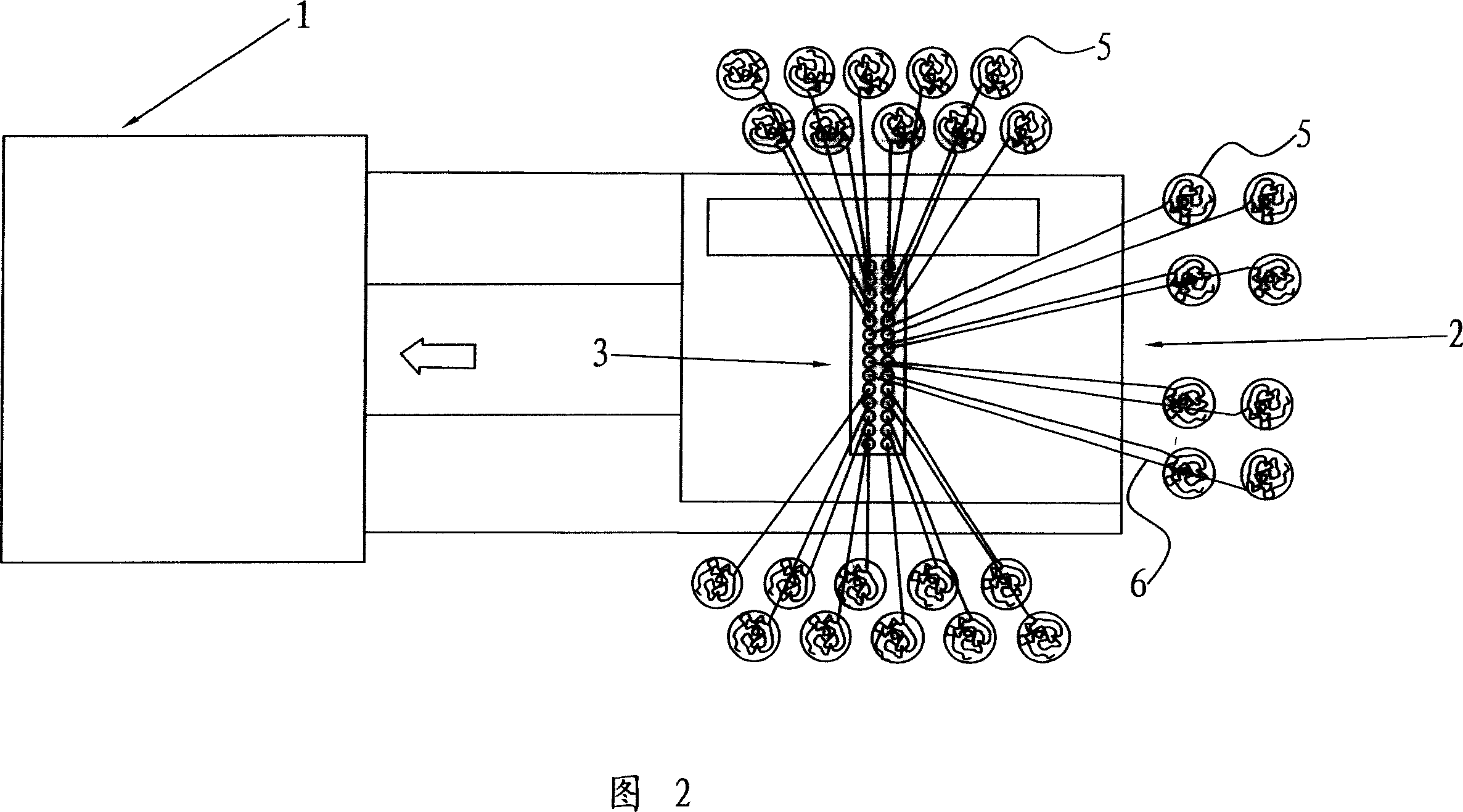
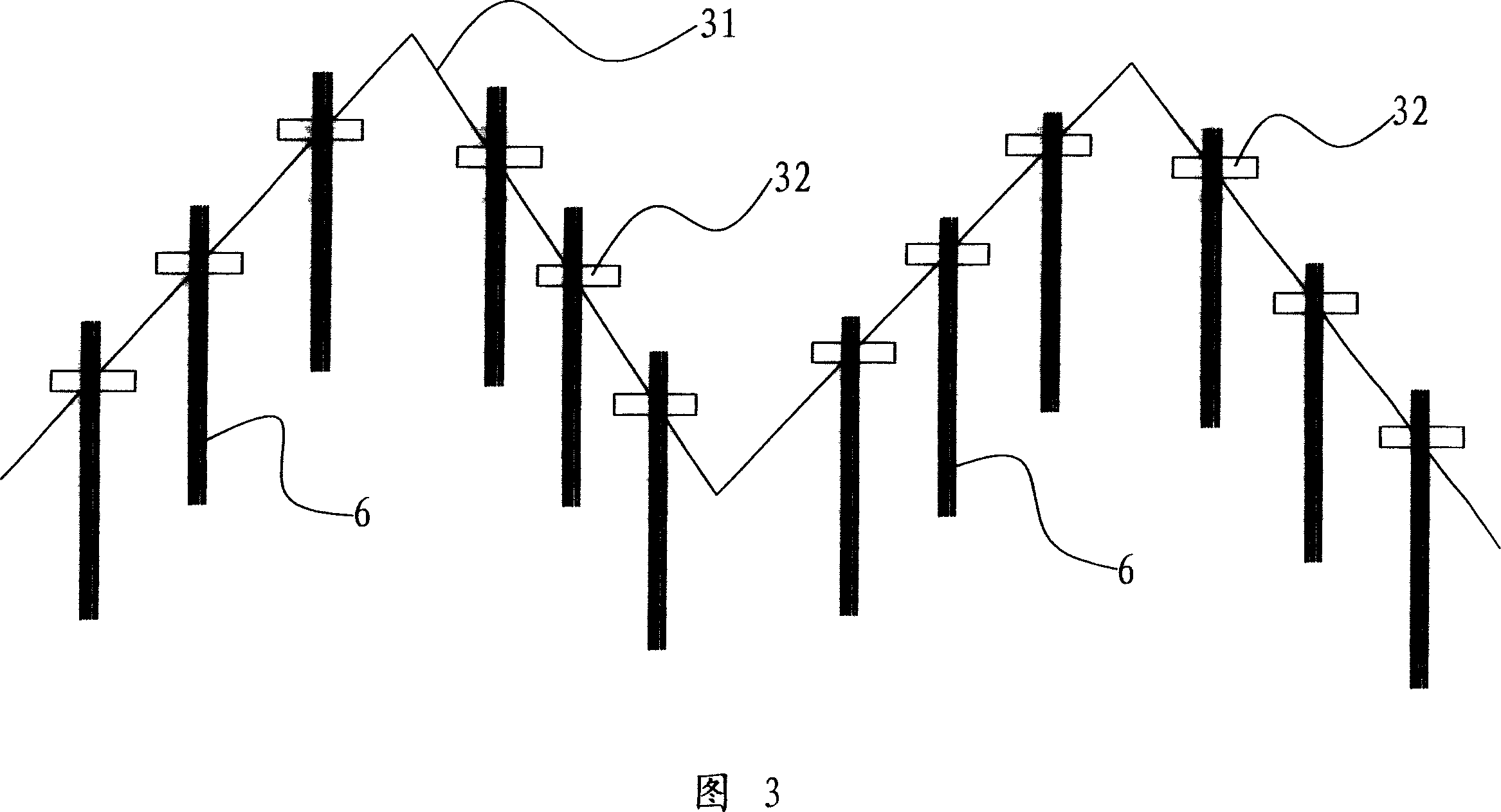
[0013] A kind of strip doubling machine shown in accompanying drawing 1-3, it comprises base 4, is arranged on described base 4 and is used for the combined drawing mechanism 2 that fiber strip 6 is combined stretching, uses In the lapping mechanism 1 that winds the fiber web 7 formed after the fiber sliver 6 is combined and stretched, the conveying direction of the fiber web 7 output by the combined drafting mechanism 2 and the winding of the lapping mechanism 1 The direction is the same, and a strip guide mechanism 3 for guiding the movement of the fiber strip 6 is arranged above the combined drafting mechanism 2, and the combined drafting mechanism 2 includes a top fixed on the base 4 Combining the drafting frame 21, at least two groups of merging drafting units 22 are arranged side by side in the combined drafting frame 21, and the described parallel arrangement refers to the The movement direction of the fiber web 7 between the mechanisms 2 is arranged front and rear, and...


PUM


Abstract

A bar ribbon lapper comprises a base, a lapping drawing device arranged on the base for lapping and drawing a plurality of fiber bars, a coiling device for coiling the lapped and drawn fiber bars, and a bar guider above the lapping drawing device for guiding the fiber bar. The lapping drawing device comprises a lapping drawing case fixed above the base, and at least two parallel groups of lapping drawing units in the lapping drawing case. The invention integrates a plurality of lapping drawing units on one lapping drawing case, while the drawing rollers are vertically arranged, to obtain compact structure and small volume.

Description

technical field [0001] The invention relates to a device for making fiber strips into fiber rolls, belonging to a strip doubling machine in textile engineering. Background technique [0002] The sliver doubling machine is a commonly used equipment for making fiber slivers into fiber rolls. The currently used slivers generally include a yarn guiding mechanism, a drafting mechanism and a lapping mechanism. The fiber sliver enters the drafting mechanism after passing through the yarn guiding mechanism. After being drawn by the drafting mechanism, it enters the coiling mechanism for winding. Due to the large number of fiber strips processed in the sliver and coiler, at least two sets of the same drafting mechanism are often required, and in order to balance the feeding draft The number of fiber slivers of the stretching mechanism requires a large distance between these drafting mechanisms. As Chinese Patent No. 95105440.6 discloses a textile machine for...

Claims


Application Information

Patent Timeline
IPC IPC(8): D01G25/00D01G23/00D01H5/22
Inventor 窦国平石英
Owner JIANGSU KAIGONG MACHINERY
Why Eureka
Try Eureka