Joint plate of combined stair bracket and combined stair bracket
A bracket connecting plate and connecting plate technology, which is applied in the direction of stairs, ladder-like structures, pedals and riser units, etc., can solve the problems that the width and height directions cannot be adjusted, troublesome, etc., and achieve the effect of convenient combination and installation and simple structure
- Summary
- Abstract
- Description
- Claims
- Application Information
AI Technical Summary
Problems solved by technology
Method used
Image
Examples
Embodiment 1
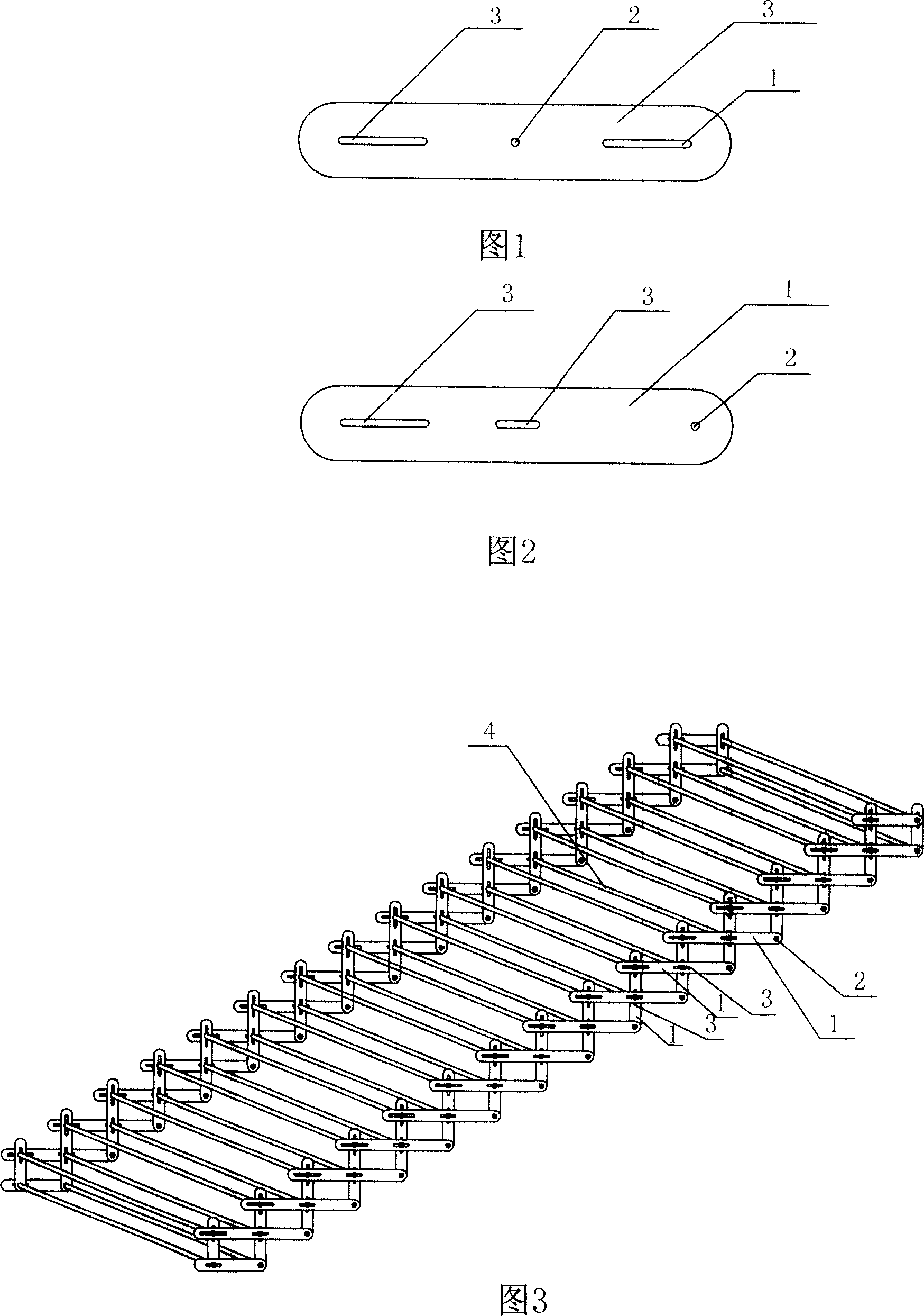
[0016] Embodiment 1: As shown in Figure 1, a connecting plate of a combined stair bracket includes a strip-shaped main body 1, and the main body 1 is provided with a fixed connection hole 2 along the length direction and two fixed connection holes extending along the length direction The groove 3 and the fixed connection hole 2 are arranged in the middle of the main body 1 , and the two fixed connection grooves 3 are respectively arranged at the two ends of the main body 1 .
Embodiment 2
[0017] Embodiment 2: As shown in Figure 2, a connecting plate of a combined stair bracket includes a strip-shaped main body 1, and the main body 1 is provided with a fixed connecting hole 2 and two fixed connecting grooves 3 extending along the length direction, and the fixed connecting groove 3 is fixed The connection hole 2 is arranged at one end of the main body 1, and the two fixed connection grooves 3 are respectively arranged at the middle and the other end of the main body 1, and the length of the fixed connection groove 3 arranged at the end of the main body 1 is 2 Double the length of the fixed connection groove 3.
Embodiment 3
[0018] Embodiment 3: A combined stair bracket, including connecting plates 1 with elongated main bodies on both sides and connecting rods 4 connecting the connecting plates 1 on both sides, the connecting plate 1 is provided with a fixed connecting hole along the length direction 2 and two fixed connection grooves 3 extending along the length direction, the fixed connection hole 2 is set at one end of the main body 1, the two fixed connection grooves 3 are respectively set at the middle and the other end of the main body 1, and are set at the end of the main body 1 The length of the fixed connecting groove 3 of the part is twice the length of the fixed connecting groove 3 arranged in the middle of the main body 1, and the connecting plates 1 on the same side are cross-overlapped, and the end of the connecting rod 6 is inserted into the connecting hole 2 or the connecting groove 3 and be fixed.
PUM
 Abstract
Description
Claims
Application Information
 - R&D
- Intellectual Property
- Life Sciences
- Materials
- Tech Scout
- Unparalleled Data Quality
- Higher Quality Content
- 60% Fewer Hallucinations
Browse by: Latest US Patents, China's latest patents, Technical Efficacy Thesaurus, Application Domain, Technology Topic, Popular Technical Reports.
© 2025 PatSnap. All rights reserved.Legal|Privacy policy|Modern Slavery Act Transparency Statement|Sitemap|About US| Contact US: help@patsnap.com

