Gearwheel and method for manufacturing a gearwheel

A gear and structure technology, applied in the field of gear and gear manufacturing, can solve problems such as unreliable deformation and poor torque synchronization

Active Publication Date: 2007-08-15
IMS GEAR SE & CO KGAA
View PDF0 Cites 17 Cited by
  • Summary
  • Abstract
  • Description
  • Claims
  • Application Information

AI Technical Summary

Problems solved by technology

In addition, the large plastic part means that at high drive torques acting on the outer ring gear, unreliable large deformations
Also, the small metal hub as the insert means that there is poor torque synchronization between the metal hub and the outer plastic ring

Method used


Image

  • Gearwheel and method for manufacturing a gearwheel

Examples


Embodiment Construction

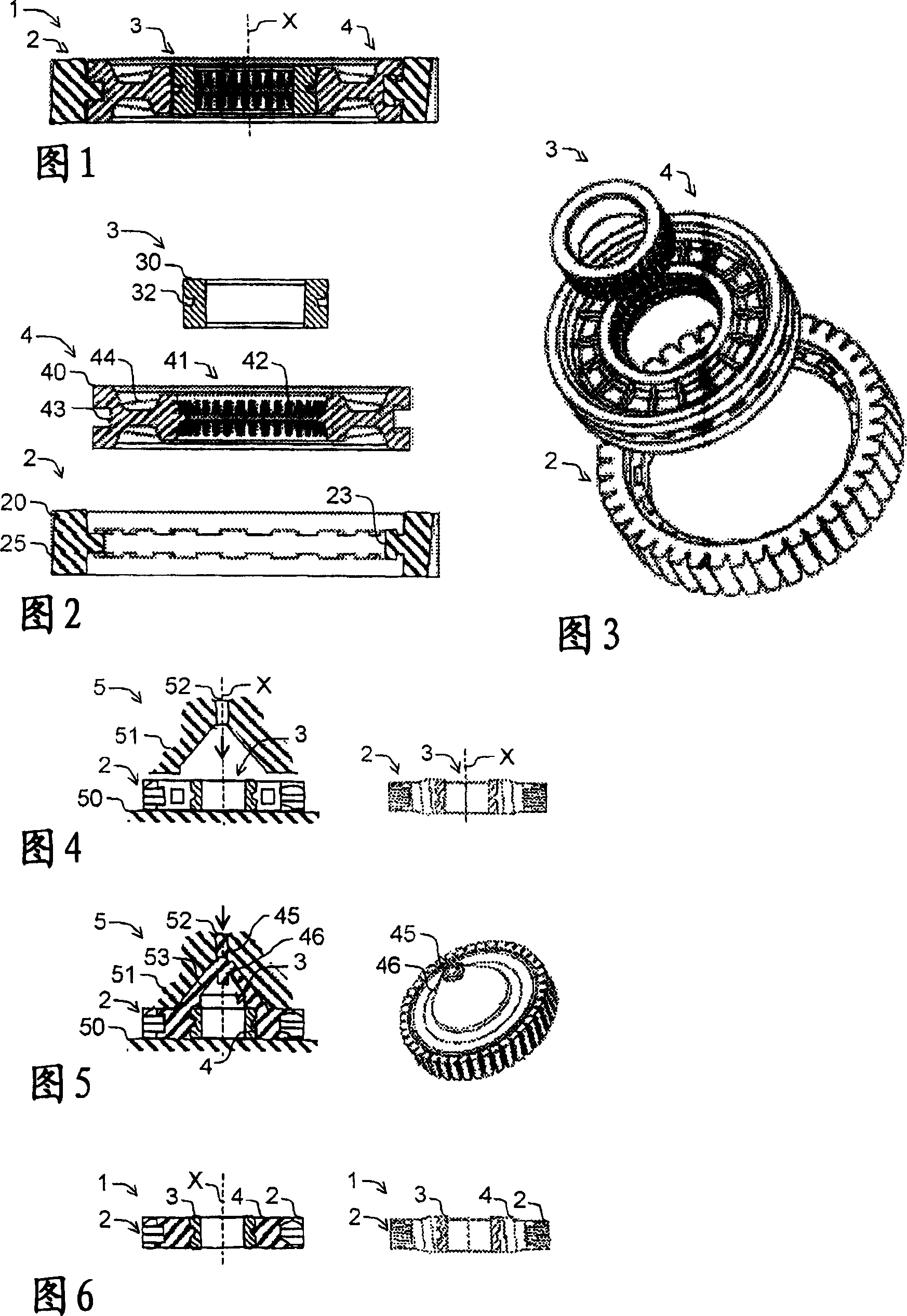
[0031] As shown in FIGS. 1-3 , an exemplary gear 1 is composed of a plurality of individual gear parts, wherein the gear 1 is exemplary composed of three parts. The gear wheel 1 has on the side an outer part 2 which forms the actual toothed ring. In this case, the outer part 2 is preferably dimensioned very thinly or with little extension in the radial direction. The gear wheel 1 has an insertion 3 on the inside, usually an insertion 3 designed as a hub. While the outer part 2 is preferably produced from a relatively soft plastic material, as is known per se for gears, the insert 3 is preferably designed as a metal hub, for example a steel hub, as is likewise known per se.

[0032] The outer circumference of the insertion part 3 is spaced apart from the inner circumference of the outer part 2 so that they can be releasably interleaved in the mold. The connection between the insertion part 3 and the outer part 2 is carried out through the connection part 4 to connect the oute...


PUM


Abstract

The invention concerns a gearwheel ( 1 ) with an external part ( 2 ), an insert ( 3 ), and a connecting part ( 4 ) for creating a form-fitting connection between the external part ( 2 ) and the insert ( 3 ), wherein the connecting part ( 4 ) is made from a material molded between the external part ( 2 ) and the insert ( 3 ). According to the method, the invention concerns a method for manufacturing a gearwheel ( 1 ), in which an external part ( 2 ) and an insert ( 3 ) are form-fittingly connected to a connecting part ( 4 ), wherein the minimum of one such connecting part ( 4 ) is molded between the external part ( 2 ) and the insert ( 3 ).

Description

technical field [0001] The invention relates to a gear having the features of the preamble of claim 1 and a method of manufacturing a gear having the features of the preamble of claim 6 . Background technique [0002] So-called EPAS gears are known, for example, from the technical field of servo steering (EPAS: Electronic Power Assisted Steering / Control with Electric Power Assist). Such gears consist of cast polyamide rings bonded to large metal hubs. Subsequently, the ring gear is machined to form a toothing on the outside of the cast polyamide ring. Furthermore, gear wheels are known in which large steel hubs are injection-moulded. A large steel or metal hub is considered to be a hub having a diameter greater than half the diameter of the gear so constructed. [0003] Thus, the known toothed wheel has an outer part which bears the actual toothed ring on the outside and an insertion which is designed in particular as a large metal hub. The connection is made by mechanic...

Claims


Application Information

Patent Timeline
Patent Type & Authority Applications(China)
IPC IPC(8): F16H55/17B29C45/14
CPCF16H55/06F16H2055/065
Inventor S・奥伯勒
Owner IMS GEAR SE & CO KGAA
Why Eureka
Try Eureka