Vertical steam boiler

A steam boiler, vertical technology, applied in steam boilers, fire tube steam boilers, water tube steam boilers, etc., can solve the problems of unreasonable heat exchange cycle process, reduced safety and service life, and high utilization rate of heat energy absorption , to achieve the effect of reasonable heat exchange cycle process, long service life and safe operation

Inactive Publication Date: 2007-08-15
石家庄市石换换热环保有限公司
View PDF0 Cites 6 Cited by
  • Summary
  • Abstract
  • Description
  • Claims
  • Application Information

AI Technical Summary

Problems solved by technology

[0002] In the existing vertical boiler with spiral heat exchanger, the upper part is a spiral heat exchanger, the outer periphery of the lower part is the pot shell, the inside of the shell is the furnace and the preheating chamber surrounding the furnace, and the high-temperature flue gas flows from the inside to the outside along the spiral flue. , the hot water preheated by the preheating chamber flows from the outside to the inside along the spiral and the water channel, and the two flow in reverse. Compared with the traditional hot water boiler, the heat energy absorption and utilization rate is high and the floor space is small, but the boiler with this structure still has the following defects : First, there is only one heat exchange system in the composition, that is, a spiral heat exchanger, and its structure limits its use as an atmospheric hot water boiler; second, low-temperature water first enters the water chamber surrounding the high-temperature furnace, and then enters the relatively low temperature In the spiral heat exchanger, the heat exchange cycle process of water is not reasonable enough; the third is that the semicircular end plate of the spiral water channel in the center of the spiral body is directly facing the top of the furnace chamber, and the bottom surface of the semicircular end plate is directly heated by the flame. Low, reduced safety and service life

Method used


Image

  • Vertical steam boiler
  • Vertical steam boiler
  • Vertical steam boiler

Examples


Embodiment Construction

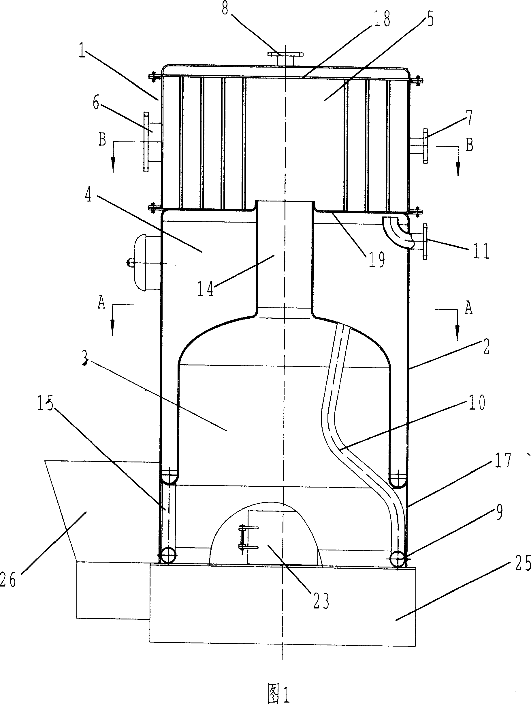
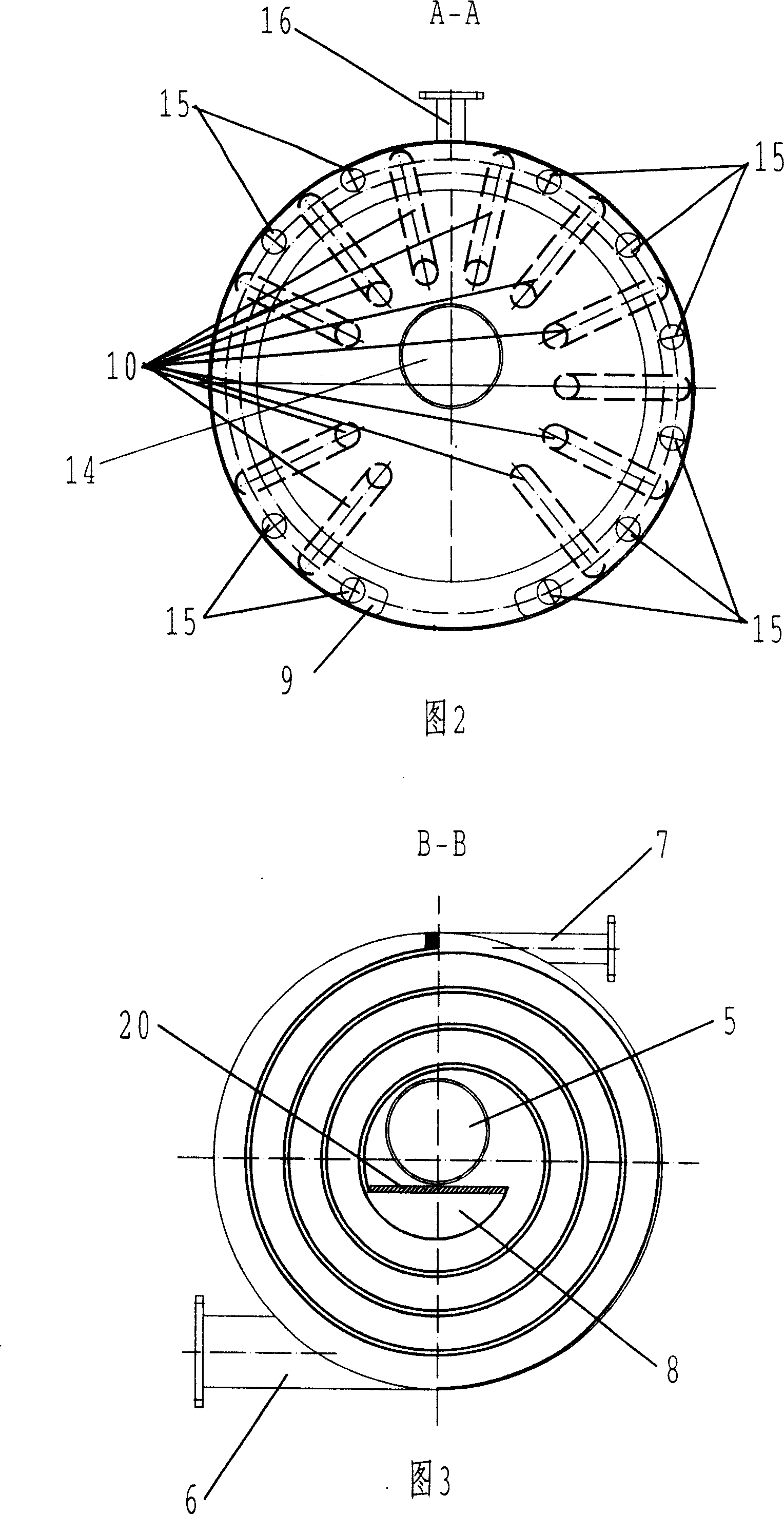
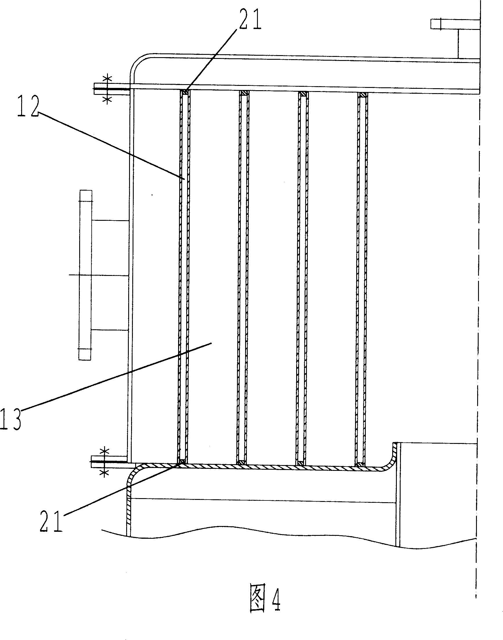
[0022] See Figures 1, 3, and 4. The spiral heat exchanger 1 is composed of a spiral sandwich body in the middle, an upper cover plate 18, and a lower bottom plate 19. The upper cover plate 18 is composed of a thin plate and an insulation layer. The spiral interlayer cavity is a spiral water channel 12, and the spiral gap between the spiral interlayers is a spiral In the flue 13, the primary hot water enters through the spiral channel inlet 7 at the outer spiral end and flows out through the central spiral channel outlet 8, and the high-temperature flue gas enters through the central spiral flue inlet 5 and is discharged from the spiral flue outlet 6 at the outer spiral end. The upper and lower ends of the spiral interlayer cavity have spiral strip sealing plates 21 to form a welded closed interlayer body. The upper and lower ends of the spiral flue 13 are in close contact with the upper cover plate 18 and the lower bottom plate 19, and no spiral strip sealing plates are provide...


PUM


Abstract

An upright steam boiler comprises a screw heat exchanger, a boiler frame, a container in the frame, and a gas space between the frame and the container, wherein the top of the container is communicated with the inlet of screw smoke channel. The invention uses a secondary water heating system, while the water tank is at the bottom of the gas space and they are communicated. The ascending tube of the water tank via the container is communicated with the gas space, a steam outlet is above the gas space, and the water tank is disposed with a secondary water inlet. The invention can use secondary water heating system to increase water temperature quickly, while in operation, low-temperature soft water first enters into the screw heat exchanger, and the generated first heating water via a water tube, the water tank and the ascending tube enters into the gas space, and hot water circulates from the low temperature area to the high-temperature area.

Description

technical field [0001] The invention relates to a vertical boiler, in particular to a vertical boiler with a spiral heat exchanger, and belongs to the technical field of boilers. Background technique [0002] In the existing vertical boiler with spiral heat exchanger, the upper part is a spiral heat exchanger, the outer periphery of the lower part is the pot shell, the inside of the shell is the furnace and the preheating chamber surrounding the furnace, and the high-temperature flue gas flows from the inside to the outside along the spiral flue. , the hot water preheated by the preheating chamber flows from the outside to the inside along the spiral and the water channel, and the two flow in reverse. Compared with the traditional hot water boiler, the heat energy absorption and utilization rate is high and the floor space is small, but the boiler with this structure still has the following defects : First, there is only one heat exchange system in the composition, that is, ...

Claims


Application Information

Patent Timeline
IPC IPC(8): F22B31/08F22B11/00
Inventor 谢建斌王徐影冯青秀霍现霞
Owner 石家庄市石换换热环保有限公司
Why Eureka
Try Eureka