Controller structure

A regulator and differentiator technology, applied in control/regulation systems, instruments, simulators, etc., to solve complex problems

Inactive Publication Date: 2007-08-15
DR JOHANNES HEIDENHAIN GMBH
View PDF1 Cites 3 Cited by
  • Summary
  • Abstract
  • Description
  • Claims
  • Application Information

AI Technical Summary

Problems solved by technology

The controller structure is complex here especially for the case where the current velocity is detected on the drive but the current position is detected directly on the object to be positioned

Method used


Image

  • Controller structure

Examples


Embodiment Construction

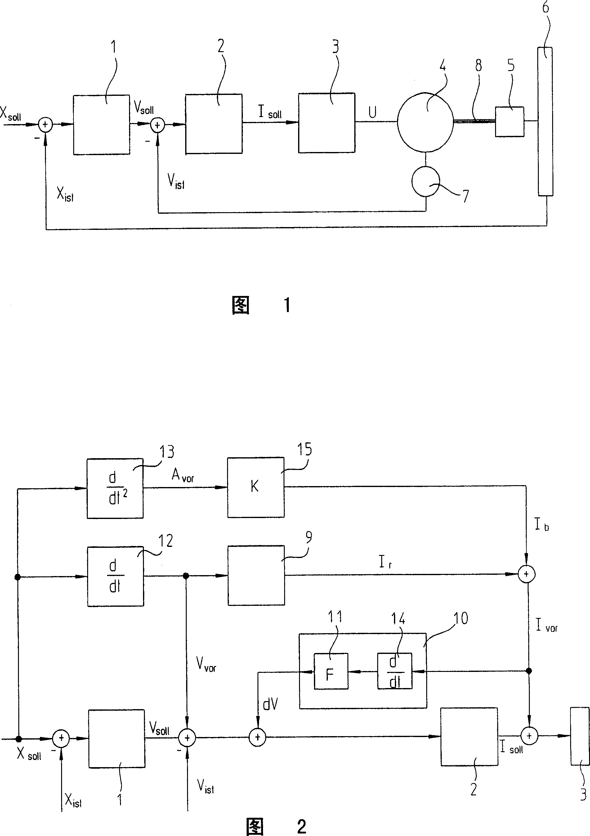
[0014] FIG. 1 shows a simplified structure of a controller according to the prior art. The difference resulting from a position setpoint value Xsoll and an actual position value Xist is fed to a position controller 1 . The position setpoint Xsoll can be obtained, for example, from a part program of a numerical control device, according to which programmed tool path is to be carried out to machine the workpiece. In this case, the actual position value Xist is acquired by means of a length measuring device 6 which detects the position of an object 5 in the direction of the axis to be adjusted. The longitudinal movement of the body 5 to be regulated is here effected by a drive or electric motor 4 , which is connected to the body 5 via a mechanical device 8 . The mechanism has a certain elasticity, so that the speed and position of the motor 4 and the object 5 do not always have to correspond to each other.

[0015] The position controller 1 produces a signal corresponding to th...


PUM


Abstract

The invention relates to a controller structure for controlling the position of an object (5), in which the object (5) is drived by a motor (4) through a mechanical installation (8). The controller structure has a position controller (1) for generation of a rotational speed reference value(Vsoll) from a position reference value(Xsoll) and a position actual value(Xist); a rotational speed controller (2) for generation of a reference current value (Isoll) from the rotational speed reference value and a rotational speed actual value (Vist); as well as circuits (9,12,13) for generation of a pre-control (Ivor) from the position reference value, wherein the pre-control (Ivor) is connected to the reference current value (Isoll). The pre-control current (Ivor) is provided to a module (10) for torsion pre-controlling, wherein the output signal (dV) of the module is added to the rotational speed reference value (Vsoll). The module (10) for torsion pre-controlling is composed by a differentiator (14) of the first derivative for forming the pre-control current (Ivor), and a second multiplier (11), in which the first derivative of the pre-control current multiplies a factor (F).

Description

technical field [0001] The invention relates to a regulator structure. Such a controller structure is used, for example, in numerical control devices, by which positioning tasks in machine tools are assisted. Thus, for example, a tool can machine a workpiece along a programmed tool path. Background technique [0002] In numerically controlled devices, a cascaded controller structure is usually used, which has a position controller, a rotational speed or speed controller and a current controller. The current specified by the current controller is supplied as a setpoint current to the drives of the corresponding axes of the machine tool in order to ultimately produce the desired movement. [0003] Usually, the position of the object to be positioned is detected by a very precise position measuring device arranged on the object to be positioned, but the rotational speed of the drive motor is detected by a rotation sensor on the drive. Due to the elasticity of the mechanism b...

Claims


Application Information

Patent Timeline
Patent Type & Authority Applications(China)
IPC IPC(8): G05B11/32G05B19/19G05B17/02
CPCG05B2219/41445G05B2219/41251G05B19/404G05B2219/41432G05B2219/41161G05B11/42
Inventor F・科哈勒B・瓦斯特尔胡伯
Owner DR JOHANNES HEIDENHAIN GMBH
Why Eureka
Try Eureka