mems capacitive relative humidity sensor and preparation method thereof

A relative humidity and sensor technology, applied in the field of MEMS capacitive relative humidity sensor and its preparation, semiconductor chip field, can solve the problem of sacrificing the chip area, achieve the effect of uniform dehumidification, short diffusion distance, and reduce hysteresis error

Active Publication Date: 2017-09-26
苏州工业园区纳米产业技术研究院有限公司
View PDF7 Cites 0 Cited by
  • Summary
  • Abstract
  • Description
  • Claims
  • Application Information

AI Technical Summary

Problems solved by technology

[0007] A heating humidity sensor involved in the patent CN 103698367A, the heating circuit is distributed around the humidity sensitive unit, sacrificing part of the chip area

Method used


Image

  • mems capacitive relative humidity sensor and preparation method thereof

Examples


Embodiment Construction

[0028] The specific implementation manners of the present invention will be further described in detail below in conjunction with the accompanying drawings and embodiments. The following examples are used to illustrate the present invention, but are not intended to limit the scope of the present invention.

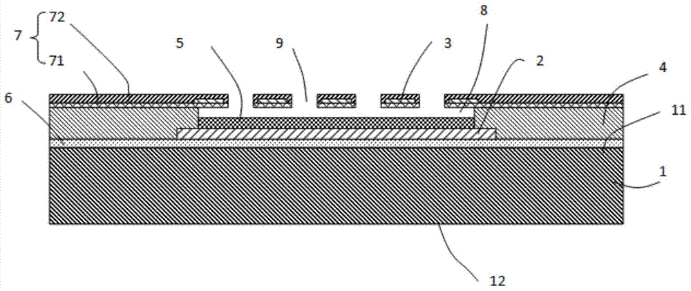
[0029] see figure 1A MEMS capacitive relative humidity sensor described in a preferred embodiment of the present invention comprises a substrate 1 with a front side 11 and a back side 12, a capacitive lower plate 2 arranged on the front side 11 of the substrate 1 and arranged on the The capacitor upper plate 3 above the capacitor lower plate 2, the insulating support body 4 supporting the capacitor upper plate 3 and the humidity sensitive layer 5 deposited on the capacitor lower plate 2 are arranged on the front surface 11 of the substrate 1 The first insulating layer 6 between the capacitor lower plate 2 and the general passivation layer 7 arranged on the insulating supp...


PUM


Abstract

The invention relates to a MEMS capacitive relative humidity sensor and a preparation method thereof, which belong to semiconductor chip technology. Since the MEMS capacitive relative humidity sensor supports the upper plate of the capacitor through an insulating support body, the upper plate of the capacitor and the humidity sensitive layer are reduced. The distance between the upper pole plate of the capacitor and the humidity sensitive layer is formed with an air gap, and on the upper pole plate of the capacitor, a number of through holes are opened to communicate the air gap with the outside, so that the upper surface of the humidity sensitive layer is completely In contact with air, the diffusion distance of water vapor molecules is short. Therefore, the humidity sensitive layer dehumidifies evenly and quickly, which can effectively reduce the hysteresis error generated during natural dehumidification. The MEMS capacitive relative humidity produced by this preparation method The humidity sensitive layer of the sensor dehumidifies evenly and quickly, which can effectively reduce the hysteresis error generated during natural dehumidification.

Description

technical field [0001] The invention relates to a MEMS capacitive relative humidity sensor and a preparation method thereof, belonging to semiconductor chip technology. Background technique [0002] Humidity sensors are widely used in many fields such as national defense aviation, meteorological detection, industrial control, and agricultural production. In recent years, miniaturized humidity sensors have gradually become the mainstream of the market. Existing miniature humidity sensors mainly include capacitive, resistive, piezoresistive and other types. Capacitive humidity sensors have been widely used in commercial fields due to their advantages of low power consumption and low cost. The development of MEMS technology provides a platform for the design and manufacture of some high-performance humidity sensors. These high-performance humidity sensors include types such as fast response, low temperature drift, and high sensitivity, which can meet the corresponding needs. ...

Claims


Application Information

Patent Timeline
Patent Type & Authority Patents(China)
IPC IPC(8): G01N27/22B81C1/00
Inventor 赵成龙
Owner 苏州工业园区纳米产业技术研究院有限公司
Why Eureka
Try Eureka