LED lamp pin welding method and equipment

A technology of LED lights and welding equipment, which is applied in welding equipment, metal processing equipment, lighting and heating equipment, etc., and can solve problems such as not being able to meet the demand of the LED market

Inactive Publication Date: 2007-08-22
HE SHAN NEO NEON LIGHTING DECORATION LTD
View PDF0 Cites 30 Cited by
  • Summary
  • Abstract
  • Description
  • Claims
  • Application Information

AI Technical Summary

Problems solved by technology

Figure 1 shows the schematic diagram of the welding method of this device. This device welds two wires to the two lamp pins of the LED at one time, and repeats the above steps mechanically, which

Method used


Image

  • LED lamp pin welding method and equipment
  • LED lamp pin welding method and equipment
  • LED lamp pin welding method and equipment

Examples


Embodiment Construction

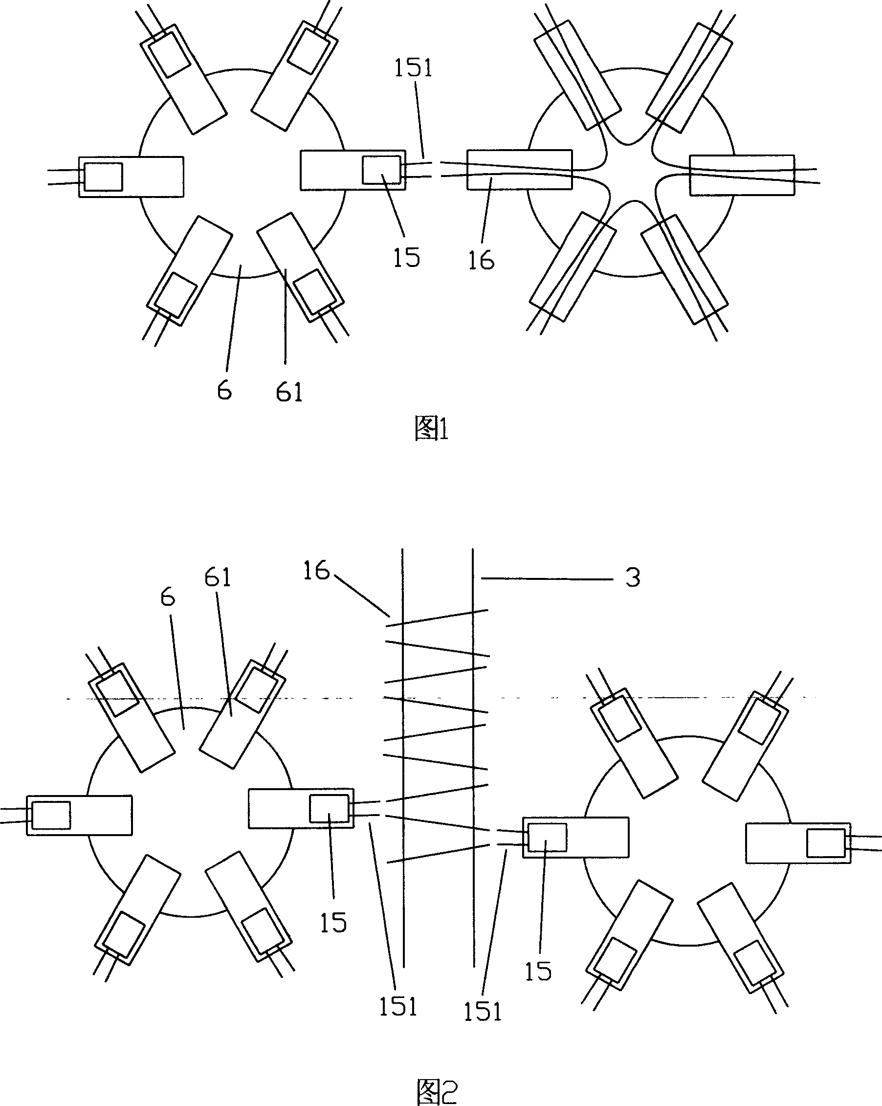
[0011] The difference between the existing welding process equipment and the present invention will be briefly described below. As shown in Figure 1 is a brief schematic diagram of the existing welding process equipment. The pretreated LED15 and wire 16 are placed on two adjacent disc-shaped clamping devices 6 respectively, the two lamp pins 151 of the LED15 are placed outwards, and the wire 16 is placed on both sides of the clamping device 6 in an arc shape. On the first clamping block 61, when the unwelded LED15 and the wire 16 were in the alignment position at the same time, the welding device welded, so that the two lamp pins 151 of the LED15 were welded to the two wires 16 respectively, and two solder joints were completed at a time.

[0012] As shown in Figure 2 is a schematic diagram of the process equipment of the present invention. The pretreated LED15 is placed on two disc-shaped clamping devices 6, while the pretreated wire 16 is placed on the side-by-side conveyor...


PUM


Abstract

The present invention relates to a LED lamp pin welding equipment. It includes machine frame, transmission mechanism positioned under the machine frame, conveying chain positioned on the machine frame, vibration plate, LED-placing device, clamping device, stripping and wire-cutting device and welding device. It is characterized by that on the above-mentioned machine frame it has two vibration plates, two LED-placing devices, two clamping devices, two stripping and wire-cutting devices and two welding devices which are respectively positioned at two sides of conveying chain. Besides, said invention also provides the welding method matched with said LED lamp pin welding equipment.

Description

technical field [0001] The invention relates to a welding method for LED lamp pins and welding equipment using the method. Background technique [0002] In the current lighting field, LEDs are more and more widely used due to their superior luminous efficiency and power saving performance. Judging from the current market situation, the demand for LED will continue to rise. In order to meet the demand, it is necessary to improve the production process of LEDs to increase the production efficiency of LEDs, and the efficiency of post-processing of LEDs also needs to be improved urgently. Shortening the completion time of a unit of LEDs will be more conducive to market competition. Now LEDs are used more often to apply them to light strings, connecting many LEDs with wires to form light strings. This process is a relatively time-consuming link in the production of the entire light string. The existing technology is all to weld the wires on the LED lamp pins. In order to shorte...

Claims


Application Information

Patent Timeline
IPC IPC(8): F21S4/00B23K3/03B23K1/00B23K1/20H01R43/02F21Y101/02F21S4/10F21Y115/10
Inventor 樊邦弘
Owner HE SHAN NEO NEON LIGHTING DECORATION LTD
Why Eureka
Try Eureka