
Electronic device

A technology for electronic devices and circuit boards, which is applied to electrical digital data processing, instruments, digital data processing components, etc., can solve problems such as damage to electronic components and failure of electronic device 100 to operate normally, and achieve good heat dissipation effects.

Inactive Publication Date: 2007-08-22
ASUSTEK COMPUTER INC
View PDF0 Cites 3 Cited by
  • Summary
  • Abstract
  • Description
  • Claims
  • Application Information

AI Technical Summary

Problems solved by technology

[0004] In addition, since the electronic components (not shown in the figure) in the electronic device 100 are the largest heat source during the operation of the electronic device 100, and when the operating temperature of the electronic components is too high, the electronic components will be damaged and the electronic device 100 cannot operate normally.

Method used


Image

  • Electronic device
  • Electronic device
  • Electronic device

Examples


Embodiment Construction

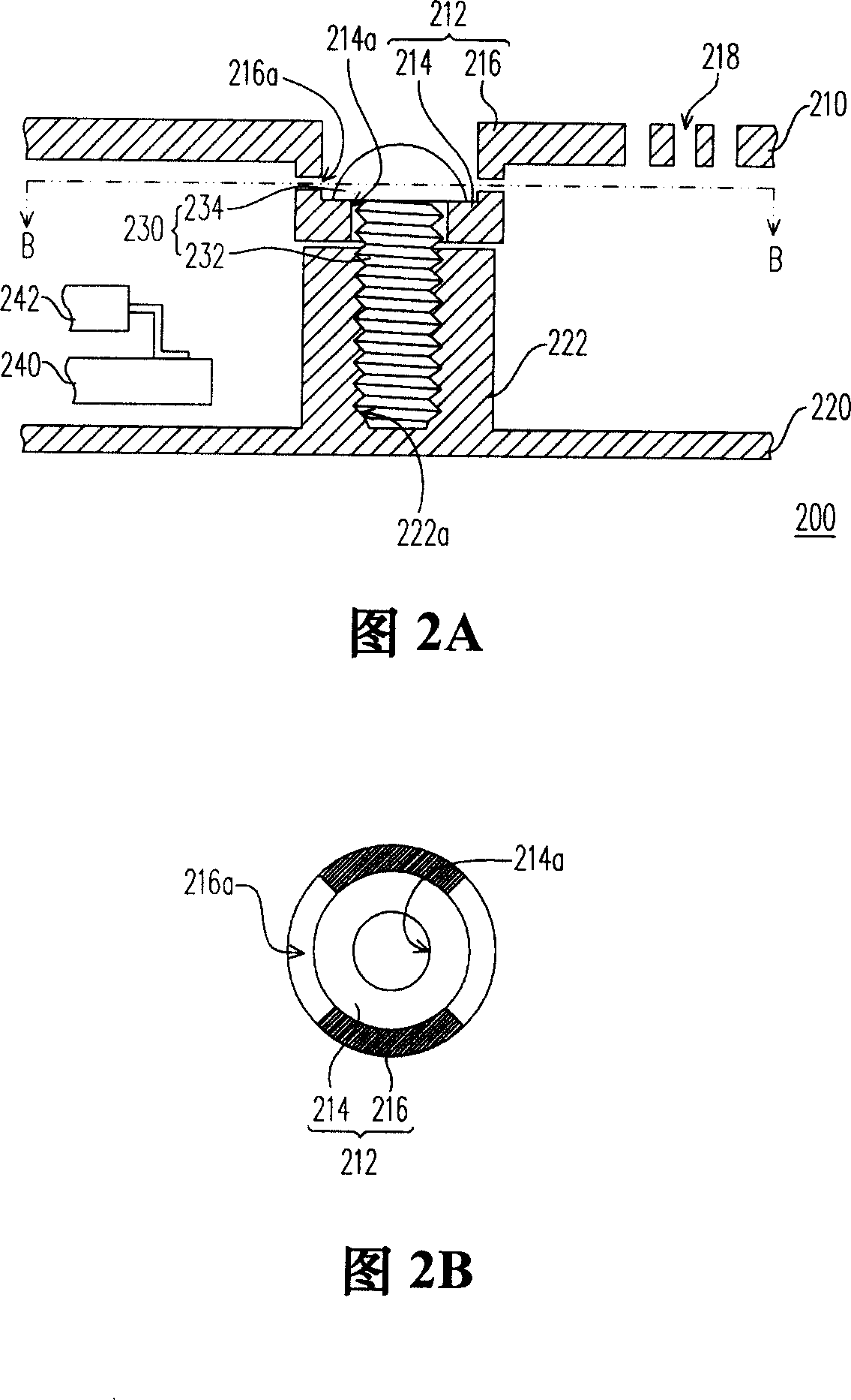
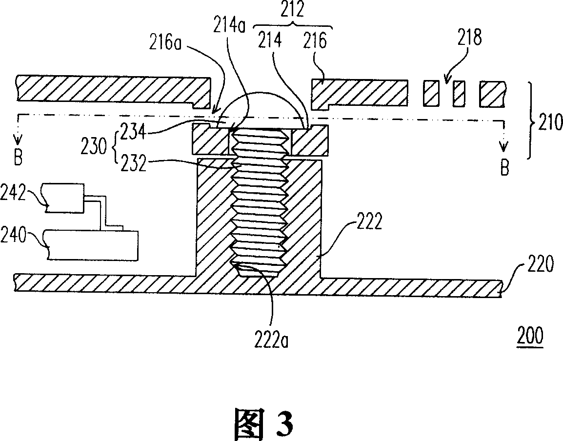
[0040] FIG. 2A is a partial sectional view of an electronic device according to an embodiment of the present invention, and FIG. 2B is a partial schematic view of the first casing along the section line B-B in FIG. 2A . Please refer to FIG. 2A and FIG. 2B at the same time. The electronic device 200 of this embodiment may be a notebook computer or other electronic devices that require heat dissipation. The electronic device 200 includes a first housing 210 , a second housing 220 and a fixing element 230 . The first housing 210 has a recessed portion 212, and the recessed portion 212 includes a bottom wall 214 and at least one side wall 216, wherein the side wall 216 is connected to the bottom wall 214, and the side wall 216 of the electronic device 200 of the present embodiment is approximately perpendicular to the bottom wall 214 . The bottom wall 214 has a through hole 214a, and the through hole 214a is suitable for allowing the fixing element 230 to pass therethrough. The ...


PUM


Abstract

An electronic device includes a first shell, a second shell and a fixed component. The first shell has a cave department, which includes the floor and at least a side wall connected with the floor. The floor has a hole, and the side wall has at least one air vent. The second shell has the fixed part, and the fixed component has the first part that gets through the hole and links the fixed part.

Description

technical field [0001] The invention relates to an electronic device, and in particular to an electronic device with a vent hole in the housing assembly structure. Background technique [0002] In recent years, with the rapid development of science and technology, the size of electronic devices has also become thinner, thinner and smaller according to the needs of users. In terms of common electronic devices, such as notebook computers, MP3 flash drives and smart phones, etc., many electronic components with different functions are arranged in the electronic devices under the limited volume, so as to The purpose of making the electronic device multifunctional is achieved. Generally speaking, most electronic devices are composed of two casings to form a receiving space for containing and protecting the circuit board of the electronic device and the electronic components thereon. [0003] FIG. 1A is a partial cross-sectional view of a known electronic device, and FIG. 1B is ...

Claims


Application Information

Patent Timeline
IPC IPC(8): G06F1/16G06F1/20
Inventor 张木财陈富明
Owner ASUSTEK COMPUTER INC
Features
  • Generate Ideas
  • Intellectual Property
  • Life Sciences
  • Materials
  • Tech Scout
  • Unparalleled Data Quality
  • Higher Quality Content
  • 60% Fewer Hallucinations
Learn More