Object detecting system, working device control system and vehicle
A detection system and working device technology, which is applied in the direction of measuring devices, radio wave measurement systems, vehicle components, etc., can solve the problems of reduced accuracy, reduced detection accuracy of vehicle occupants, deviations, etc.
- Summary
- Abstract
- Description
- Claims
- Application Information
AI Technical Summary
Problems solved by technology
Method used
Image

Examples
no. 1 approach
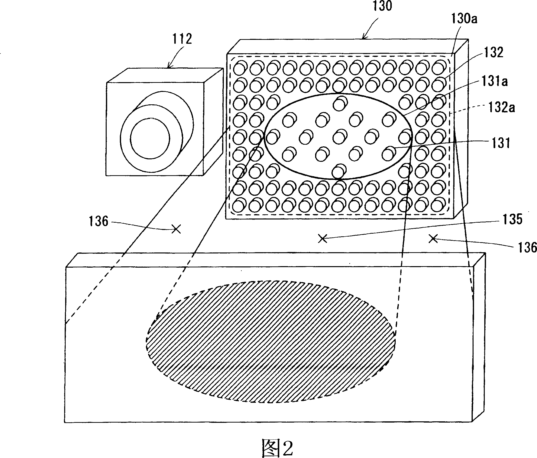
[0066]As shown in FIG. 2 , the lighting device 130 of the first embodiment has a structure in which a plurality of light emitting lamps are arranged on a facing surface 130 a facing an object. The first light source 131 is formed by a plurality of light emitting lamps arranged in a central area 131a of the facing surface 130a, and the second light source 132 is formed by a plurality of light emitting lamps arranged in an outer peripheral area 132a of the outer periphery of the central area 131a. In the present embodiment, the number of light emitting lamps per unit area (arrangement density of light emitting lamps) in the first light source 131 is smaller than that of the second light source 132 (lower arrangement density). In addition, the following structure is formed: the light emitted from the first light source 131 and reflected by the object C passes through the central portion of the objective lens opening area of the optical lens 114 of the camera 112 and enters the c...
no. 2 approach
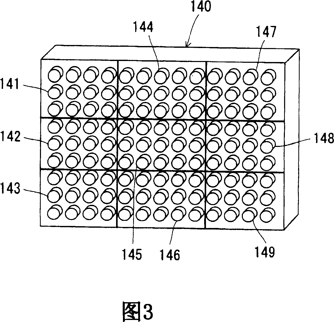
[0073] Next, the structure of the lighting device 140 of the second embodiment is as shown in FIG. 3 . In this lighting device 140, a plurality of light emitting lamps are formed and divided (divided) into a first light source 141, a second light source 142, a third light source 143, a fourth light source 144, a fifth light source 145, a sixth light source 146, a seventh light source 147. A structure of nine light sources of the eighth light source 148 and the ninth light source 149. In this embodiment, the number of light emitting lamps per unit area (arrangement density of light emitting lamps) in each of the first to ninth light sources 141 to 149 is the same. In addition, in this lighting device 140 , it is possible to independently and variably control the light emission form (light quantity, light emission pattern) of each light source.
[0074] The specific control of the lighting device 140 having such a configuration will be described with reference to FIG. 4 . FIG....
no. 3 example
[0082] Next, the structure of the lighting device 150 of the third embodiment is shown in FIG. 5 . In this lighting device 150 , a plurality of light emitting lamps are divided (divided) into three light sources of a first light source 151 , a second light source 152 , and a third light source 153 . In this embodiment, the first light source 151 is disposed facing the driver's seat area 151a, and constitutes a light source for distributing light to an object on the driver's seat (corresponding to the "driver's seat side light emitting unit" in the present invention). In addition, the second light source 152 is disposed facing the passenger's seat area 152a, and constitutes a light source for distributing light to an object on the passenger's seat (corresponding to the "passenger's seat side light emitting unit" in the present invention). Furthermore, the third light source 153 is disposed facing the rear seat area 153a, and constitutes a light source for distributing light to ...
PUM
 Abstract
Description
Claims
Application Information
PatSnap Eureka turns technology decisions into work you can execute. Powered by our Innovation Knowledge Graph, it runs expert workflows across engineering, life sciences, materials and intellectual property. Get your review-ready output in minutes.


