Method and device for compressing a gaseous medium

A technology for compressing gas and gas media, applied in pressure pumps, petroleum industry, machines/engines, etc., can solve problems such as high production and maintenance costs, achieve the effect of prolonging service life and avoiding safety problems

Inactive Publication Date: 2007-08-22
LINDE AG
View PDF0 Cites 8 Cited by
  • Summary
  • Abstract
  • Description
  • Claims
  • Application Information

AI Technical Summary

Problems solved by technology

[0004] Especially when compressing hydrogen, natural gas and high-purity media or when for some reason it is necessary to prevent and / or do not expect the media to be compressed to be contaminated by the driving medium, it is necessary to cooperate with precise cylinders and pistons and corresponding effective dynamic sealing systems ; but such systems generally result in high production and maintenance costs

Method used


Image

  • Method and device for compressing a gaseous medium

Examples


Embodiment Construction

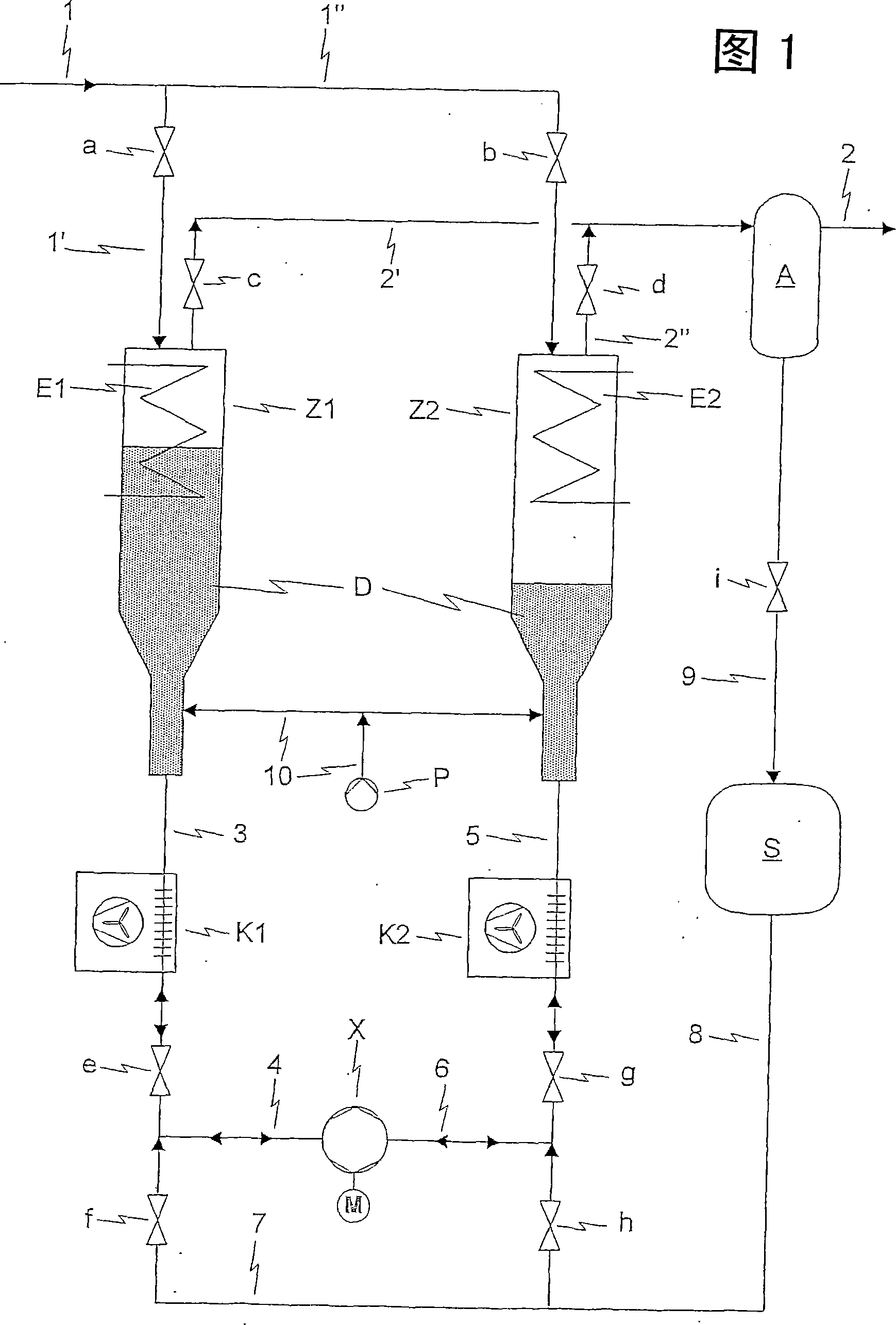
[0026] The gaseous medium to be compressed is conveyed to the cylinders Z1 and Z2 via the pipes 1, 1' and 1". In the above-mentioned pipes, the inlet valves a and b are arranged. After the compression is completed, the compressed gaseous medium is passed from the cylinders Z1 and Z2 through the discharge pipes 2' and 2" are discharged, valves c and d are likewise provided in the discharge pipe.

[0027] The compressed gaseous medium is separated in a separating device A from any liquid entrained from the cylinders Z1 and Z2 , which will be described in more detail below, and is then conveyed via line 2 to its further use and / or intermediate storage.

[0028] A suitable liquid D for compressing the gaseous medium is arranged inside the cylinders Z1 and Z2. Cylinders Z1 and Z2 are connected via lines 3 to 6 and a hydraulic pump X driven by an electric motor M.

[0029] The fluid levels in the cylinders Z1 and Z2 are varied by means of the hydraulic pump X in such a way that one...


PUM


Abstract

The invention relates to a method and device for compressing a gaseous medium, particularly hydrogen. According to the invention, the compressing (Z1, Z2) of the gaseous medium ensues by using a liquid (D). The liquid (D) used is one in which the gaseous medium does not dissolve and / or one that can be separated from the gaseous medium without residues. To this end, the liquid (D) used is an ionic liquid, a high-boiling hydraulic oil or a liquid having a very low vapor pressure.

Description

technical field [0001] The invention relates to a method for compressing a gaseous medium, especially hydrogen. [0002] The invention also relates to a device for compressing a gaseous medium, especially hydrogen. Background technique [0003] Reciprocating compressors or reciprocating compressor systems are currently commonly used in such methods and devices for compressing gaseous media. Piston compressors require corresponding sealing systems for separating the medium to be compressed from the (drive) medium driving the pistons, for example hydraulic oil. [0004] Especially when compressing hydrogen, natural gas and high-purity media or when for some reason it is necessary to prevent and / or do not expect the media to be compressed to be contaminated by the driving medium, it is necessary to cooperate with precise cylinders and pistons and corresponding effective dynamic sealing systems ; but such systems generally result in high production and maintenance costs. For ...

Claims


Application Information

Patent Timeline
Patent Type & Authority Applications(China)
IPC IPC(8): F04F1/06F04F1/10
CPCF04F1/10C10N2220/04F04F1/06C10N2020/077
Inventor 罗伯特·阿德勒格奥尔格·西伯特
Owner LINDE AG
Why Eureka
Try Eureka