X-ray CT imaging method and X-ray CT apparatus

A technology for X-ray and image display devices, which is used in measurement devices, instruments for radiological diagnosis, and material analysis using radiation, which can solve problems such as manufacturing difficulties and achieve high-resolution effects

Inactive Publication Date: 2007-08-29
GE MEDICAL SYST GLOBAL TECH CO LLC
View PDF0 Cites 2 Cited by
  • Summary
  • Abstract
  • Description
  • Claims
  • Application Information

AI Technical Summary

Problems solved by technology

However, since the demand for higher resolution of the X-ray detector becomes more urgent, if one tries to achieve twice fine resolution in the channel direction and twice fine resolution in the row direction, then it is necessary to The X-ray detector or X-ray detector module of Fig. 15 is divided into each channel direction or each row direction, just as in the case of the X-ray detector or X-ray detector module of Fig. 16, from the X-ray detector or X-ray This is a problem from the point of view of the difficulty of manufacturing the detector module

Method used


Image

  • X-ray CT imaging method and X-ray CT apparatus
  • X-ray CT imaging method and X-ray CT apparatus
  • X-ray CT imaging method and X-ray CT apparatus

Examples


example 2

[0215] Furthermore, a case will be described with respect to Embodiment 3, in which the resolution in the channel direction is increased to improve the spatial resolution of the tomographic image by interleaving adjacent rows of X-ray detector data.

Embodiment 1

[0217] A case will be described with respect to Embodiment 1 in which data is collected by the multi-row X-ray detector 24 or the two-dimensional X-ray surface detector 24 using the X-ray detector module shown in FIG. 23 .

[0218] In this embodiment, since the data is collected by the multi-row X-ray detector 24 or the two-dimensional X-ray surface detector 24 using the X-ray detector module shown in FIG. X-ray detector data collected by X-ray detectors in X-ray detector.

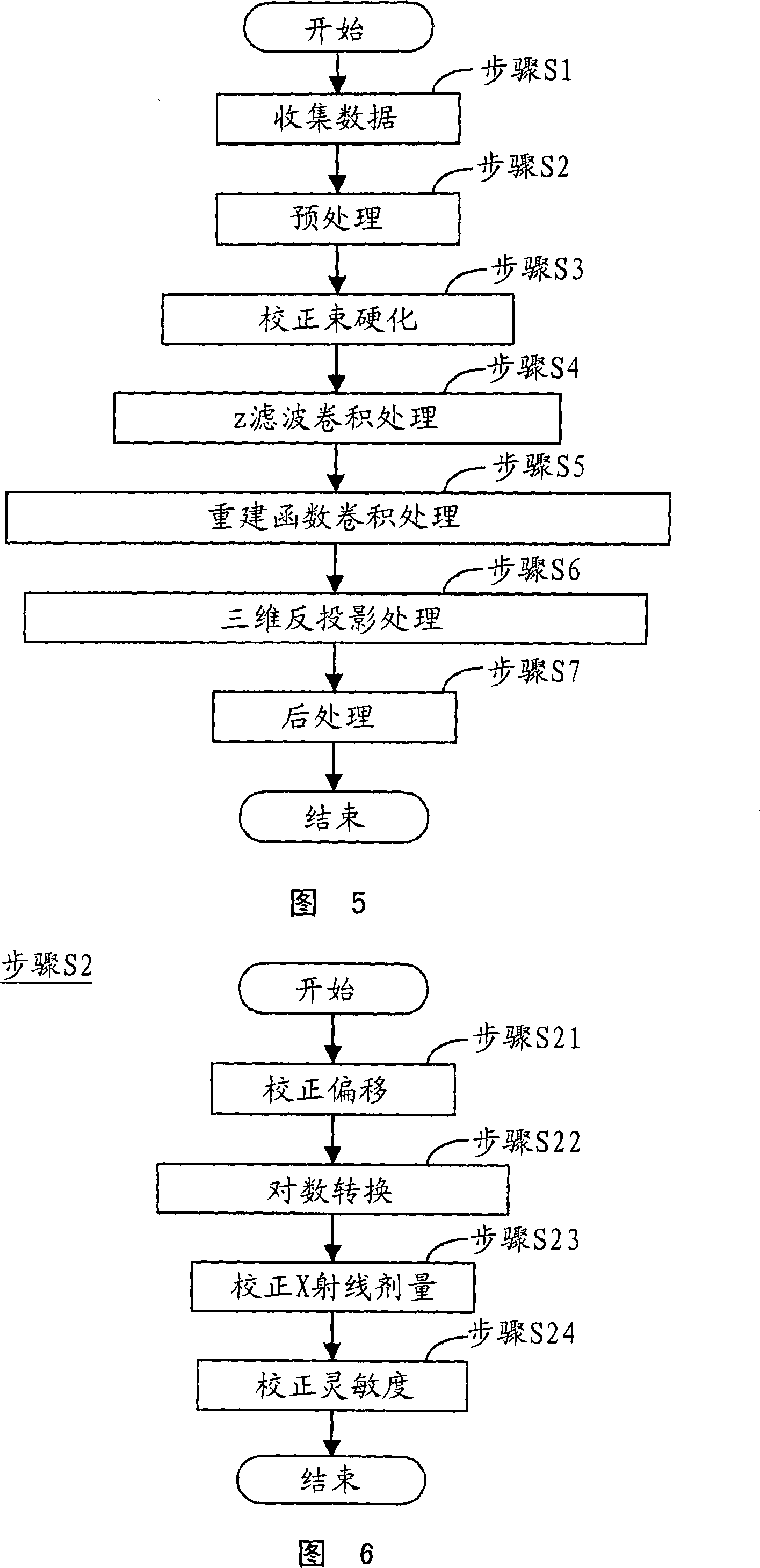
[0219] The preprocessing and reconstruction function convolution processing in this case includes the preprocessing of step S2 of FIG. 5 as described above, and the beam hardening correction of step S3, the Z filter convolution processing of step S4, the step Reconstruction function convolution processing in S5 and post-processing in step S7.

[0220] In addition, in the image reconstruction of the three-dimensional back-projection process in step S6, the three-dimensional back-projection process is perfo...

Embodiment 2

[0330] Embodiment 2 shown in FIG. 36 is a form of Embodiment 1 in which the peripheral portion of the X-ray detector module is made easier to manufacture.

[0331] In Example 2, a houndstooth structure substantially similar to that in Example 1 was used.

[0332] Also in Embodiment 2, the preprocessing, reconstruction function convolution, etc. are similar to the preprocessing of step S2, the beam hardening correction of step S3 and the z-filter convolution processing of step S4, the reconstruction function convolution of step S5 and the step S7 for post-processing.

[0333] In the three-dimensional back-projection processing of step S6, by similarly using the three-point weighted addition processing of Embodiment 1, data extraction can be completed without blurring the projection data, and image reconstruction can be achieved without deteriorating the obtained by three-dimensional back-projection processing Spatial resolution of X-ray tomography images.

[0334] The method ...


PUM


Abstract

Enhancement of the resolution of tomograms obtained by conventional scanning (axial scanning), cine-scanning, helical scanning or variable-pitch helical scanning by the X-ray CT apparatus using a multi-row X-ray detector or a two-dimensional X-ray area detector of a matrix structure is to be realized by a simple method. An X-ray CT apparatus is realized in which a multi-row X-ray detector or a two-dimensional X-ray area detector of a matrix structure with a small amount of processing work, and image reconstructing device capable of providing high-resolution tomograms by image reconstruction is provided.

Description

technical field [0001] The present invention relates to an X-ray CT device for medical use or an X-ray CT device for industrial use, an X-ray CT (computed tomography) imaging method and an X-ray CT device, and to improving the X-ray CT The resolution of the tomographic images produced only by conventional scanning (axial scanning), cine-scanning, helical scanning or variable-pitch helical scanning X-ray detectors. Background technique [0002] Generally, in an X-ray CT apparatus based on a multi-row X-ray detector or an X-ray CT apparatus using a matrix-structured two-dimensional X-ray surface detector, a multi-row X-ray detector or a square spot as shown in FIG. 15 is used. A two-dimensional X-ray surface detector of matrix or rectangular lattice structure, as described in JP-A No. 193750 / 2000. In this case, where the resolution of the X-ray detectors is to be increased, the width of each detector must be reduced to l / n (where n is an integer) in both the channel direction...

Claims


Application Information

Patent Timeline
Patent Type & Authority Applications(China)
IPC IPC(8): A61B6/03G01N23/04
CPCA61B6/032A61B6/027G01N23/046G01N2223/419G01N2223/612A61B6/03A61B6/00
Inventor 泷浦泰郎西出明彦藤重高志
Owner GE MEDICAL SYST GLOBAL TECH CO LLC
Why Eureka
Try Eureka