Cast-in-situ hollow board

A hollow slab and cast-in-place concrete technology, which is applied to floors, building components, buildings, etc., can solve problems such as the inability to effectively ensure that the width of the floor is consistent with the design width, affect the construction quality of the floor, and cannot arrange hollow carcass. Achieve the effects of guaranteed pouring quality, low cost and easy production

Inactive Publication Date: 2007-08-29
湖南邱则有专利战略策划有限公司
View PDF3 Cites 0 Cited by
  • Summary
  • Abstract
  • Description
  • Claims
  • Application Information

AI Technical Summary

Problems solved by technology

But when this kind of hollow carcass is applied to the floor construction, the hollow carcass cannot be accurately arranged in the middle layer of the floor, which affects the construction quality of the floor
For this reason, the patent number is ZL01215092.4, and the utility model patent titled "Building Components" discloses a building component that is a polyhedron, which can be hollow or solid. It is arranged in the middle layer of the floor, and the outer wall of the polyhedron is provided with protruding legs, so that when the floor is poured, the legs can ensure that the hollow multi-faceted main cavity is just at

Method used


Image

  • Cast-in-situ hollow board
  • Cast-in-situ hollow board
  • Cast-in-situ hollow board

Examples


Embodiment Construction

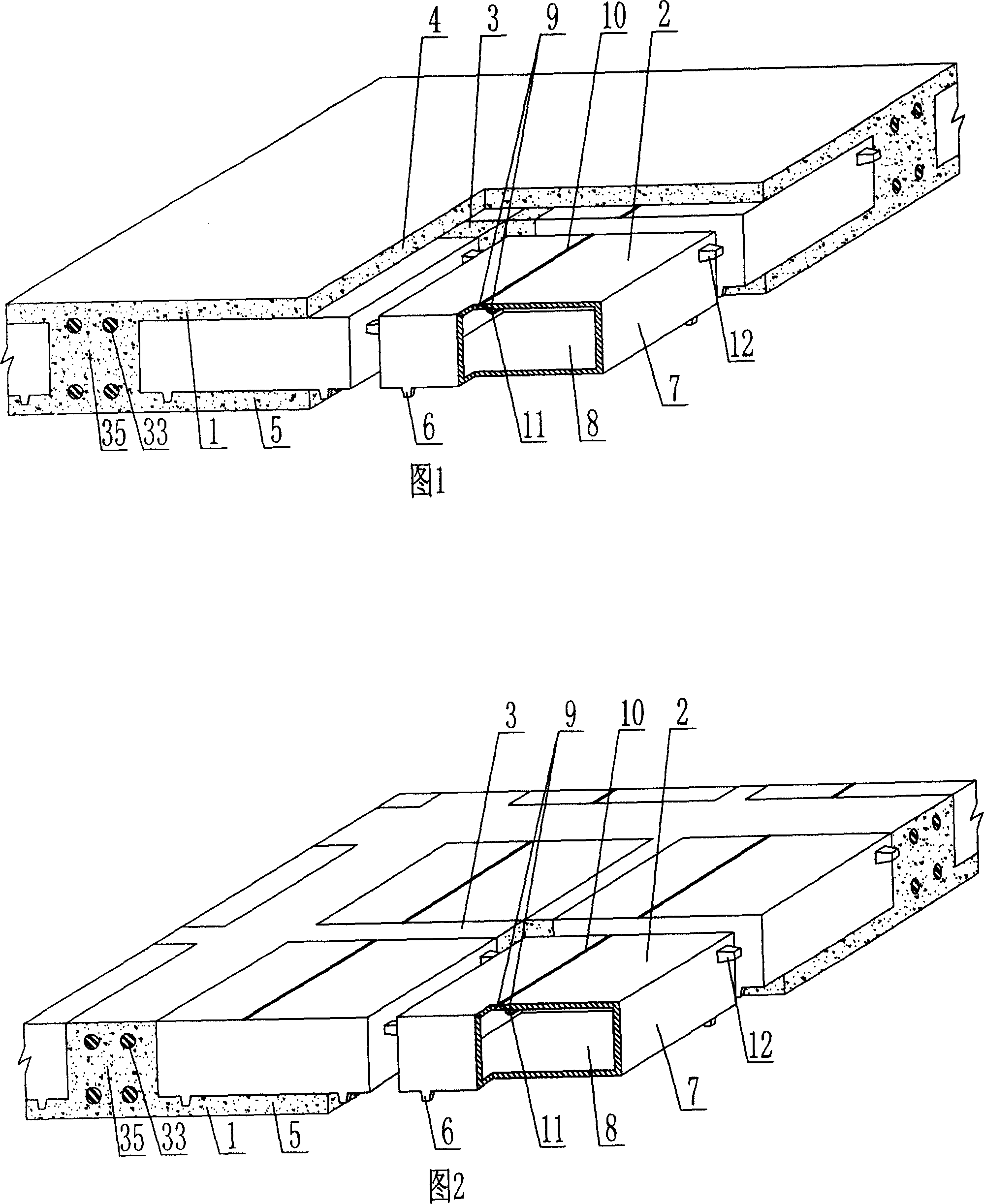
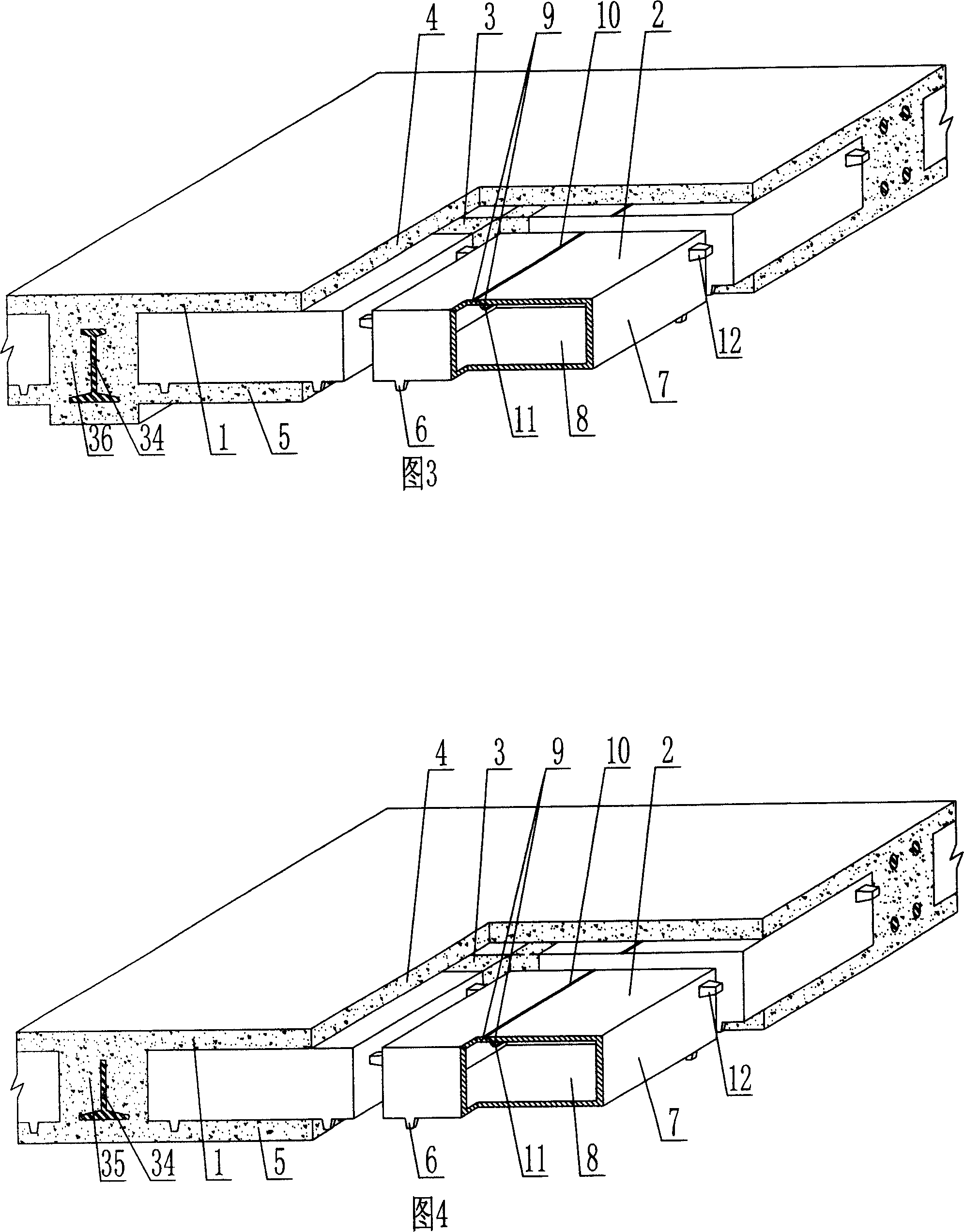
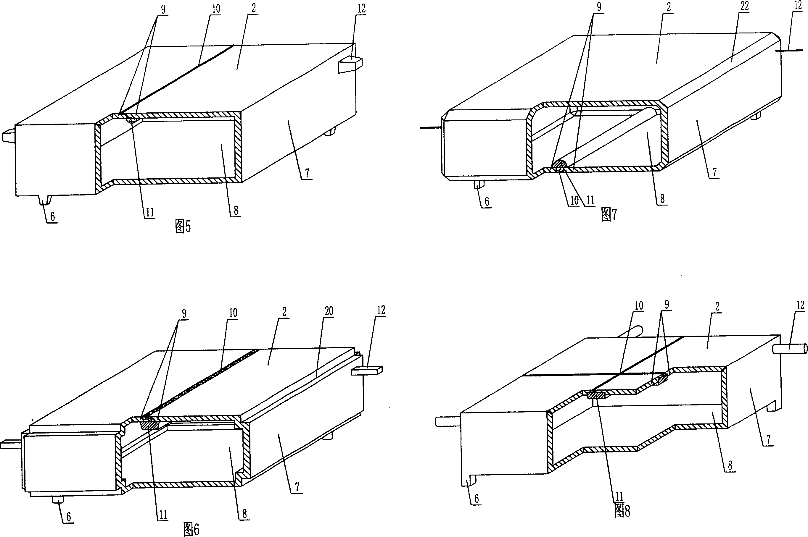
[0084] The present invention will be further described below in conjunction with the accompanying drawings and embodiments.

[0085] As shown in the accompanying drawings, the present invention comprises a reinforced concrete 1 and a hollow carcass 2, the hollow carcass 2 is wrapped in the reinforced concrete 1, the hollow carcass 2 are arranged alternately, and there are cast-in-situ reinforced concrete ribs 3 between them. It is an upper plate 4 of cast-in-place reinforced concrete, under which is a lower plate 5 of cast-in-place reinforced concrete. The hollow carcass 2 is provided with supporting feet 6. The supporting feet 6 are arranged on the outer wall 7 of the bottom surface of the hollow carcass 2. The outer wall 7 encloses The hollow carcass 2 formed with a cavity 8 is characterized in that the outer wall 7 of the hollow carcass 2 has a cementing belt 10 joined to the edge of the slurry body 9 of the outer wall 7, and the cementing belt 10 is located in the cavity 8 ...


PUM


Abstract

The invention is a cast-in-site concrete hollow slab, comprising reinforced concrete, and hollow bodies, where the hollow bodies are wrapped in the reinforced concrete and alternate with cast-in-site reinforced concrete ribs, cast-in-site reinforced concrete top plate and infrabasal slab are on and under the hollow bodies respectively, the hollow body is equipped with support foot, the support foot is arranged on the bottom outer wall of the hollow body, the hollow body is formed by outer walls, and it is characterized in that: the outer wall of the hollow body has cementation belt bonded with sides of pulp body of the outer wall, the position of in-cavity cementation belt is stacked with a prefabricated mould, and the side outer wall of the hollow body is equipped with rib space width limiting piece. Thus, the hollow body has features of easy to make, high production efficiency, good integrity, low cost, easy to assure the pouring quality of cast-in-site concrete building covers.

Description

(1) Technical field [0001] The invention relates to a cast-in-place concrete hollow slab. (2) Background technology [0002] At present, the cast-in-place concrete hollow floor is a widely used floor structure. The lightweight permanent tire molds filled in it include various hollow tubes and boxes, and the boxes are hollow or solid. For example, the patent No. ZL99249798.1, which the applicant applied for on November 29, 1999, is a utility model patent named "fiber-reinforced thin-walled member for reinforced concrete filling", which discloses a thin-walled formwork member, including an upper plate, The surrounding side walls, the lower bottom, and the upper plate, the surrounding side walls and the lower bottom form a polyhedral cavity. Another example is that the patent No. is ZL00203695.9, and the name is called "combined concrete hidden rib floor slab" utility model patent, which discloses a formwork member in its specification, which can be solid or hollow, and its sh...

Claims


Application Information

Patent Timeline
IPC IPC(8): E04B5/18E04B5/36
Inventor 邱则有
Owner 湖南邱则有专利战略策划有限公司
Why Eureka
Try Eureka