

Display device
A technology for display devices and display devices, which can be used in identification devices, static indicators, optics, etc., and can solve problems such as degradation of display quality
- Summary
- Abstract
- Description
- Claims
- Application Information
AI Technical Summary
Problems solved by technology
Method used
Image

Examples
Embodiment 1
[0236] (Fabrication of the first anisotropic scattering film)
[0237] First, a polyethylene terephthalate (PET) film (trade name: COSMOSHINE (registered trademark), model: A4300, manufactured by Toyobo Co. ) after the liquid resin was ejected from the edge portion, the liquid resin was solidified to form a partition wall with a height of 0.2 mm. Then, after dropping the photopolymerizable composition of the following composition in the area|region surrounded by a partition, it covered with another PET film.
[0238] "Composition of Photopolymerizable Composition"
[0239] 2-(perfluorooctyl (perfluorooctyl))-ethyl acrylate 50 parts by weight
[0240] 1,9-nonanediol diacrylate 50 parts by weight
[0241] 2-Hydroxy-2-methyl-1-phenylpropan-1-one 4 parts by weight
[0242] Afterwards, for the liquid film with a thickness of 0.2mm sandwiched between the upper and lower sides by the PET film, the UV spot light source (trade name: L2859-01, manufactured by Hamamatsu Photonics Co....
Embodiment 2
[0264] FIG. 9 is a schematic perspective view showing the configuration of a VA-mode liquid crystal display device 100a according to Embodiment 2 of the present invention. The relationship between the lamination of each film and the axial direction is shown in Figure 9 and Table 2.
[0265] [Table 2]
[0266] Components
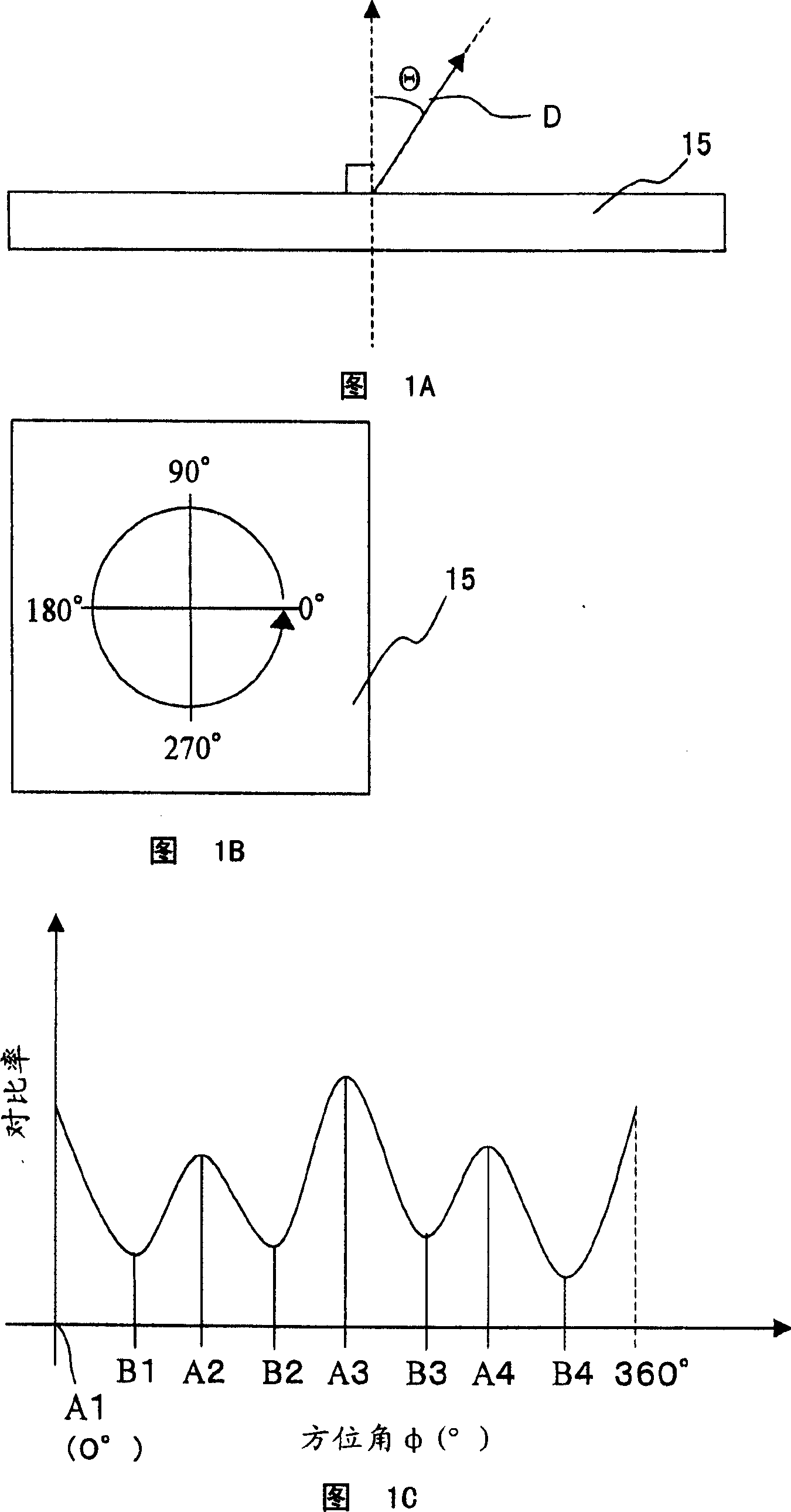
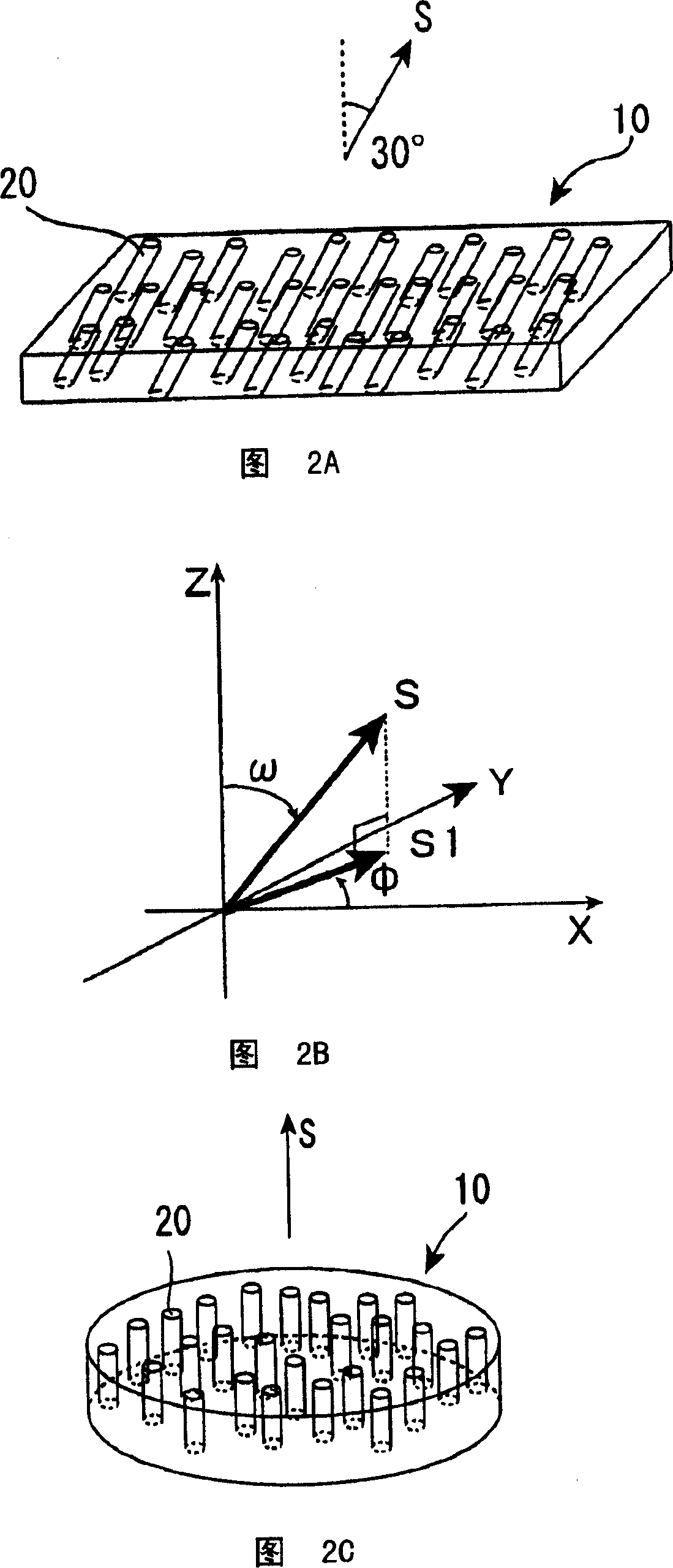
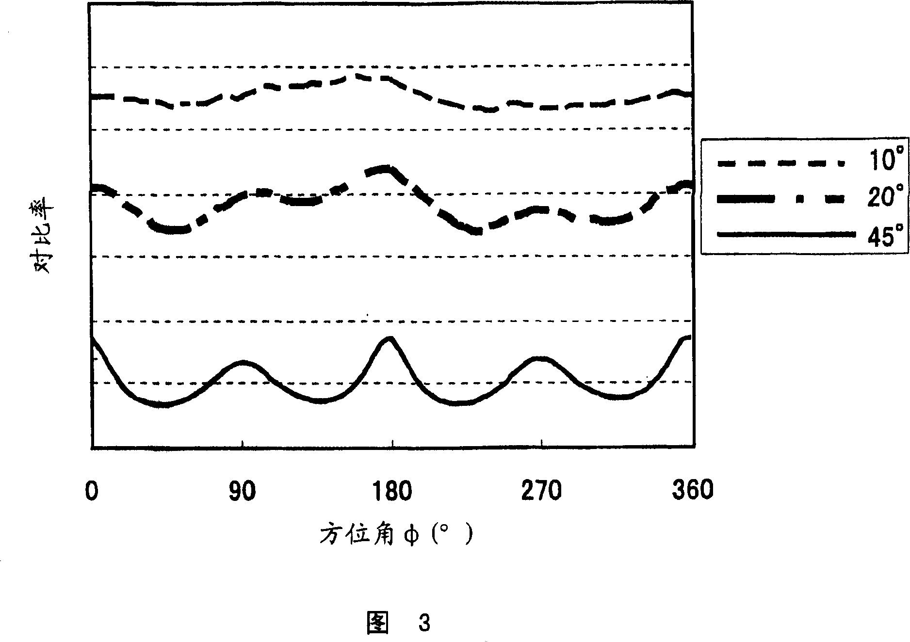
Azimuth Φ
The first anisotropic scattering film 10a (the axis of the scattering central axis
Azimuth S 1 )
90 degrees
Polarizer 3a-observation side (absorption axis a)
0~180 degrees
Second retardation film 12b (slow axis s)
90~270 degrees
VA mode liquid crystal cell 11a (tilt orientation of liquid crystal molecules)
45, 135, 225, 315 degrees
3rd retardation film 12c (slow axis s)
0~180 degrees
Polarizing element 3a - back side (absorption axis a)
90~270 degrees
[0267] (Fabrication of VA Mode Liquid Crystal Display Device 15a)
[0268] First, the support film on the s...
Embodiment 3
[0275] FIG. 10 is a schematic perspective view showing the configuration of a VA-mode liquid crystal display device 100a according to Embodiment 3 of the present invention. Figure 10 and Table 3 show the relationship between the lamination of each film and the axial direction.
[0276] [table 3]
[0277] Components
Azimuth Φ
The first anisotropic scattering film 10a (the axis of the scattering central axis
Azimuth S 1 )
90 degrees
1st polarizer 13a-observation side (absorption axis a)
0~180 degrees
VA mode liquid crystal cell 11a (tilt orientation of liquid crystal molecules)
45, 135, 225, 315 degrees
4th retardation film 12d (slow axis s)
0~180 degrees
1st polarizer 13a-back side (absorption axis a)
90~270 degrees
[0278] (Fabrication of VA Mode Liquid Crystal Display Device 15a)
[0279] First, the 4th retardation film 12d is pasted on the backlight side of the VA mode liquid crystal cell 1...
PUM
| Property | Measurement | Unit |
|---|---|---|
| thickness | aaaaa | aaaaa |
| thickness | aaaaa | aaaaa |
| thickness | aaaaa | aaaaa |
Abstract
Description
Claims
Application Information