Supercharge Your Innovation With Domain-Expert AI Agents!

Light emission device

A light-emitting device and electron emission technology, applied in the installation/support/configuration/insulation of electrode components, discharge tubes, eliminating unnecessary temperature effects, etc., can solve the deformation of electron beam path trajectory, uneven light emission of fluorescent screen, light-emitting device Problems such as deterioration of brightness uniformity

Inactive Publication Date: 2007-08-29
SAMSUNG SDI CO LTD
View PDF0 Cites 0 Cited by
  • Summary
  • Abstract
  • Description
  • Claims
  • Application Information

AI Technical Summary

Problems solved by technology

Accordingly, the electron beam moving around the spacer may be attracted or repelled by the spacer, and thus the path trajectory of the electron beam may be deformed
As a result, the fluorescent screen portion around the spacer may not emit light uniformly
In this way, the brightness uniformity of the light emitting device deteriorates

Method used


Image

  • Light emission device
  • Light emission device
  • Light emission device

Examples


Embodiment Construction

[0021] In the following detailed description, only certain exemplary embodiments of the present invention are shown and described, by way of illustration. As those skilled in the art would realize, the described exemplary embodiments may be modified in various ways, all without departing from the spirit or scope of the present invention. Accordingly, the drawings and description are to be regarded as exemplary in nature, and not restrictive.

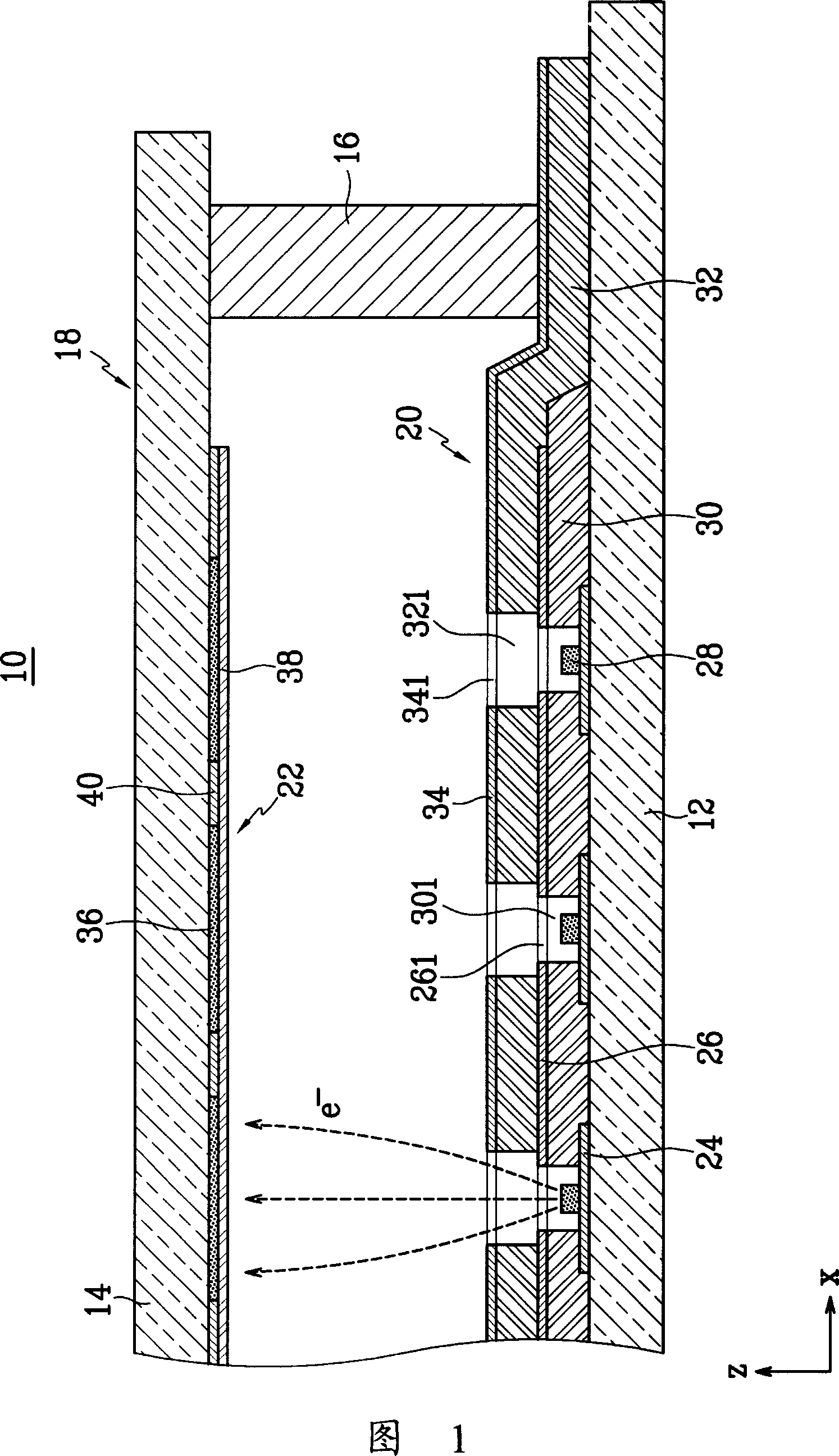
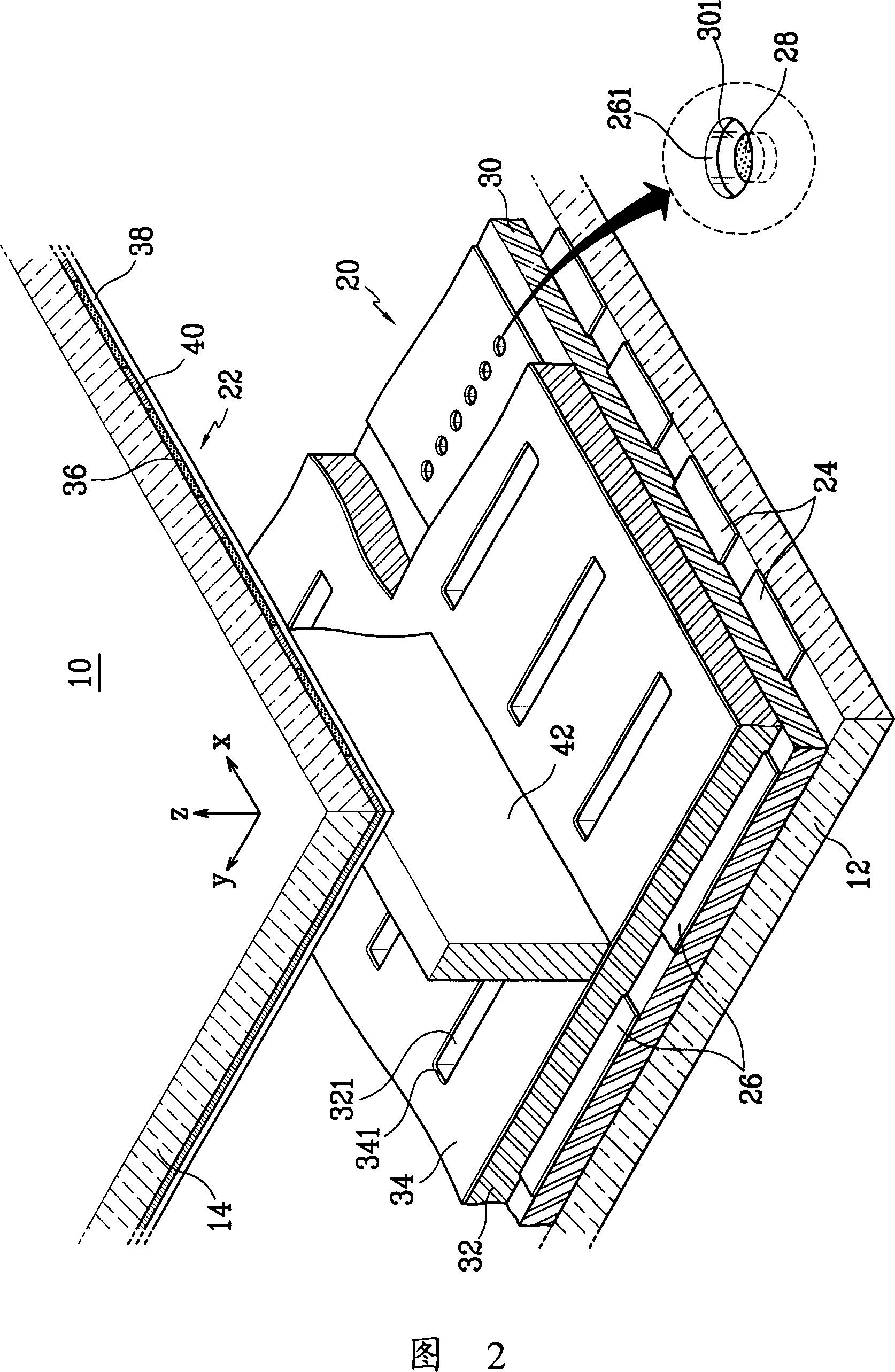
[0022] In an exemplary embodiment of the present invention, a light emitting device may be considered as a device for emitting light to the outside thereof. More specifically, lighting devices may be used to convey information by displaying symbols, words, numbers and / or images. In addition, the light emitting device may be used as a light source for emitting light to a passive-type display panel.

[0023] Referring to FIGS. 1 and 2 , a light emitting device 10 according to a first embodiment of the present invention includes a first s...


PUM


Abstract

In an embodiment of the present invention, a light emission device includes a vacuum vessel that includes first and second substrates facing each other and a sealing member for sealing the first and second substrates, an electron emission unit that is located on an inner surface of the first substrate and includes a plurality of electron emission regions and a plurality of driving electrodes for controlling the electron emission of the electron emission regions, a light emission unit that is located on an inner surface of the second substrate, and a heat dissipation layer that defines an uppermost layer of the electron emission unit and has a thermal conductivity of at least 2 W / cmK, a portion of the heat dissipation layer extending out of the vacuum vessel through a region between the sealing member and the first substrate.

Description

technical field [0001] The invention relates to a light emitting device. Background technique [0002] A device capable of emitting light toward its exterior may be considered a light emitting device. This light emitting device has a front substrate and a rear substrate, wherein a phosphor layer and an anode electrode are formed on the front substrate, and a driving electrode and an electron emission region are formed on the rear substrate. The light emitting device emits visible light by exciting the phosphor layer by electrons emitted from the electron emission region. [0003] In the light emitting device, a sealing member is provided between the front and rear substrates to seal them together, thereby forming a vacuum container. The interior of the vacuum vessel is evacuated to maintain approximately 10 -6 Torr vacuum pressure. A high pressure caused by a pressure difference between the outside and inside of the vacuum container is applied to the vacuum container. A...

Claims


Application Information

Patent Timeline
IPC IPC(8): H01J31/12
CPCH01J1/30H01J1/88H01J29/006H01J2201/30453
Inventor 陈成焕朴哲皓朴真民俞升浚姜正镐李受京李元一郑刚植
Owner SAMSUNG SDI CO LTD
Features
  • R&D
  • Intellectual Property
  • Life Sciences
  • Materials
  • Tech Scout
  • Unparalleled Data Quality
  • Higher Quality Content
  • 60% Fewer Hallucinations
Learn More