Dynamic dimming circuit for splicing large-area field emission backlight

A field emission and dynamic dimming technology, applied in static indicators, instruments, etc., can solve the problems of high power consumption, short life, narrow color gamut, etc., and achieve the effect of low energy consumption, long service life and simple circuit

Active Publication Date: 2011-02-16
FUZHOU UNIV
View PDF4 Cites 17 Cited by
  • Summary
  • Abstract
  • Description
  • Claims
  • Application Information

AI Technical Summary

Problems solved by technology

However, cold-cathode fluorescent lamps contain metal mercury that is harmful to the environment, narrow color gamut, insufficient brightness uniformity, short life, large volume, and high power consumption, which are gradually inhibiting their application in the field of

Method used


Image

  • Dynamic dimming circuit for splicing large-area field emission backlight
  • Dynamic dimming circuit for splicing large-area field emission backlight
  • Dynamic dimming circuit for splicing large-area field emission backlight

Examples


Embodiment Construction

[0015] The present invention will be further described below in conjunction with the accompanying drawings and implementation examples.

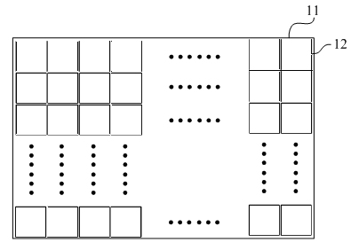
[0016] Please refer to figure 1 , figure 1 It is a schematic diagram of the overall structure of the spliced ​​large-area field emission backlight of the present invention. The backlight 11 includes a plurality of grid-type field emission backlight units 12, and all the backlight units 12 can be square, triangular, rectangular, trapezoidal, or regular polygonal. etc. are arranged according to certain rules, and each backlight unit is relatively independent, and driving signals can be applied separately without affecting each other.

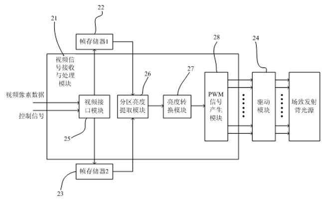
[0017] figure 2 It is an overall schematic diagram of a dynamic dimming circuit of a spliced ​​large-area field emission backlight of the present invention. As shown in the figure, the dynamic dimming circuit mainly includes three parts, a video signal receiving and processing module 21, a frame storage Modu...


PUM


Abstract

The invention relates to a dynamic dimming circuit for splicing large-area field emission backlight. The backlight is formed by splicing a plurality of triode field emission backlight units with certain regular shapes, wherein each backlight unit is relatively independent. The dynamic dimming circuit is characterized by comprising a video signal receiving and processing module, a frame storage module and a driving module, wherein the video signal receiving and processing module generates a luminance control signal of each field emission backlight unit according to the received video signal; the frame storage module is used for storing video image data and has a data caching effect; and the driving module performs current and voltage amplification on the luminance control signals so as to drive the field emission backlight.

Description

technical field [0001] The invention relates to a liquid crystal display device, in particular to a dynamic dimming circuit of a spliced ​​large-area field emission backlight, which belongs to the field of backlight, and also belongs to the field of video signal processing and control and the field of drive of field emission devices. Background technique [0002] At present, liquid crystal display (LCD) has been widely used in TVs, mobile phones, computers, monitors and other equipment. As an indispensable part of LCD, backlight is mainly used at present. LED) assembled. However, cold-cathode fluorescent lamps contain metal mercury that is harmful to the environment, narrow color gamut, insufficient brightness uniformity, short life, large volume, and high power consumption, which are gradually inhibiting their application in the field of large-area backlights. However, semiconductor light-emitting diode backlight sources require heat sinks, which have problems such as high...

Claims


Application Information

Patent Timeline
IPC IPC(8): G09G3/34G09G3/36
Inventor 林志贤郭太良姚剑敏叶芸张永爱徐胜陈志龙
Owner FUZHOU UNIV
Why Eureka
Try Eureka