
Card connector

A card connector, plug-in card technology, applied in the direction of connection, parts of the connection device, protective grounding/shielding device of the connection part, etc., can solve problems such as card misoperation, and achieve the effect of preventing secondary discharge

Inactive Publication Date: 2007-08-29
DDK LTD
View PDF3 Cites 3 Cited by
  • Summary
  • Abstract
  • Description
  • Claims
  • Application Information

AI Technical Summary

Problems solved by technology

[0008] However, in the structure like the patent document, before discharging from the above-mentioned antistatic countermeasure contact (terminal) to the frame ground (FG) or the substrate, the above-mentioned antistatic countermeasure contact (terminal) and the connecting bridge made of metal Discharge occurs at a small gap between
Once the secondary discharge occurs, noise will be generated, and the noise will be applied to the signal line, causing the card to malfunction. There are problems that need to be solved as described above.

Method used


Image

  • Card connector
  • Card connector
  • Card connector

Examples


Embodiment Construction

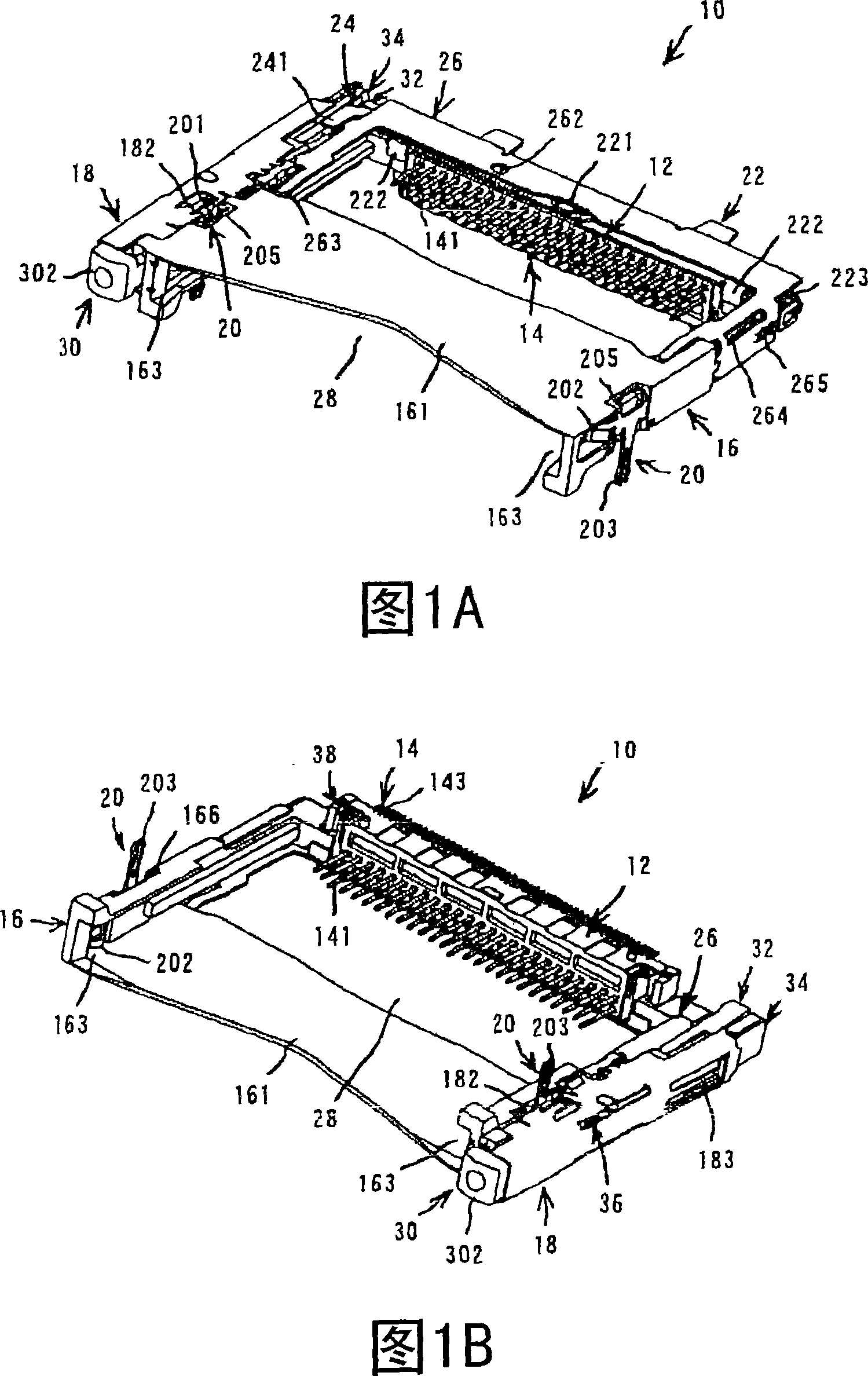
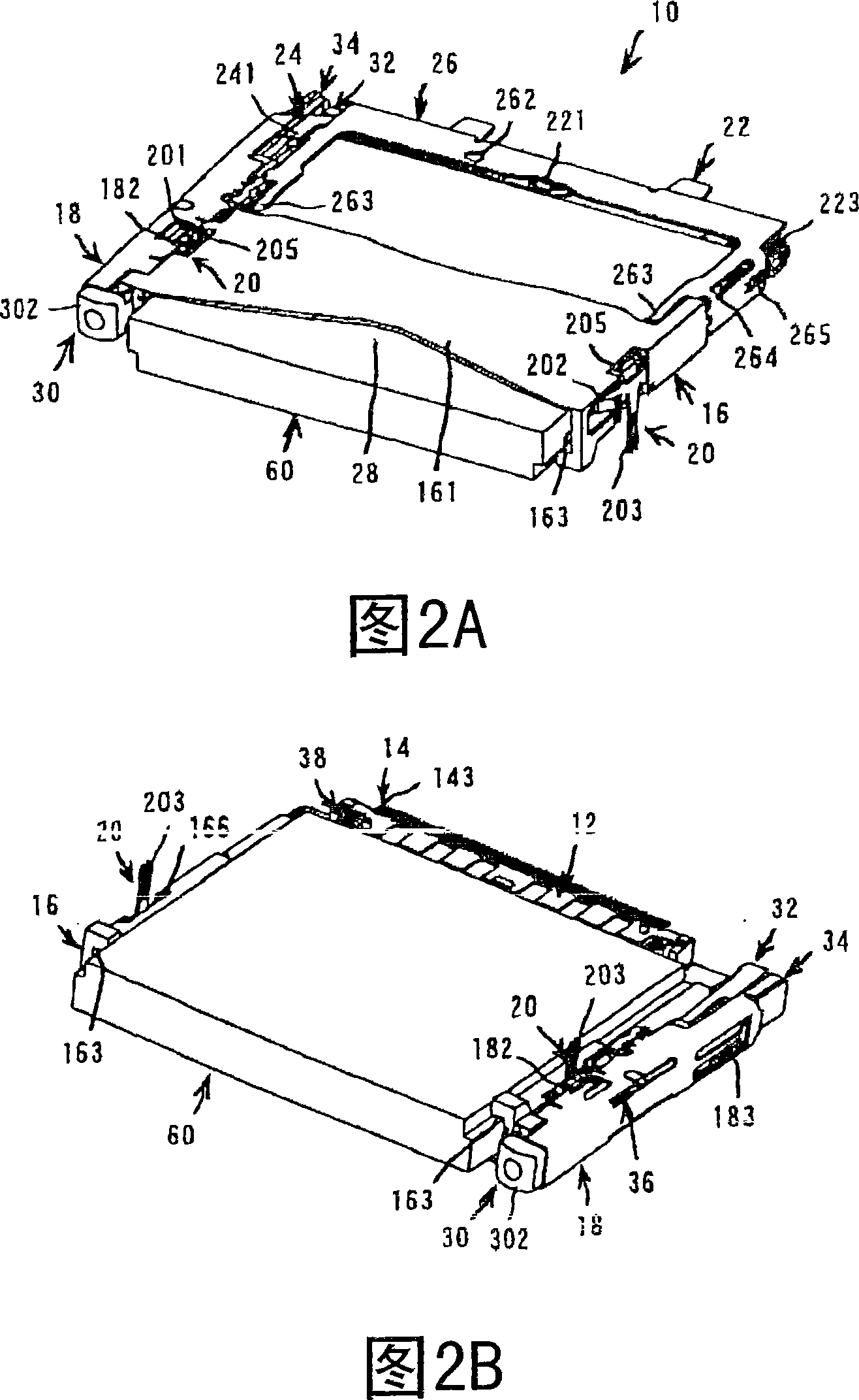
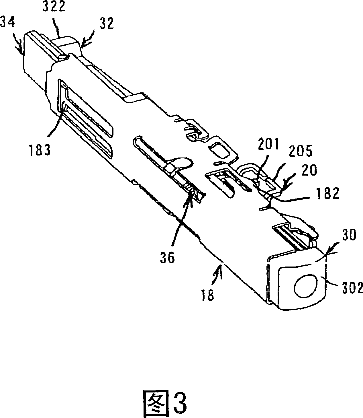
[0059] An embodiment of the present invention will be described based on FIGS. 1 to 13 . This embodiment takes inserting a CF flash memory card (registered trademark) as an example. 1(A) is a perspective view of the card connector of the present invention viewed from above in the card insertion direction, and (B) is a perspective view of the card connector of the present invention viewed from below in the card insertion direction. Fig. 2 (A) is the perspective view of the card connector of the present invention seen from above the card insertion direction in the state of inserting the card, (B) is in the state of inserting the card, viewed from the bottom of the card insertion direction. Perspective view of the invented card connector. 3 is a partially enlarged perspective view of a state where a terminal is in contact with an assembly in a state where an eject button, a cam pin frame, a heart-shaped cam plate, and an elastic body are assembled in a housing. Fig. 4(A) is a p...


PUM


Abstract

A card connector into and from which a card is inserted and removed, includes a plurality of contacts each having a contact portion to contact the card, a housing arranging and holding the contacts and having a fitting opening for inserting the card, a guide frame formed integrally with or separately from the housing and having guide portions for guiding the card to the contacts, a shell enclosing that part of the guide frame in which removing device is installed for removing the card from the card connector, and terminals arranged on the side of the leading end of the fitting opening for preventing troubles caused by static electricity. One of the terminals is provided with an extending piece extending onto the side opposite from the connection portion to be connected to a substrate. The shell is provided with an extending portion adapted to contact the extending piece. The card connector thus constructed is free from secondary discharge.

Description

technical field [0001] The present invention relates to a card connector used in electronic / electric equipment such as a personal computer or a printer, and particularly relates to a structure for implementing ESD (static electricity) countermeasures. Background technique [0002] In the past, there were different cards as various information media, and a connector was attached to the information device, and the storage information of the medium was extracted or stored through the connector. [0003] In addition, when connecting with a card, the connector is provided with a fitting port into which the card can be inserted, and the contact part of the contact is protruded in the fitting port, and the above-mentioned card is brought into contact with the contact part to obtain electrical conduction. structure. When the card is pulled out from the connector, in order to reduce the portion protruding from the connector to the card, an ejection (pulling out) mechanism such as Pa...

Claims


Application Information

Patent Timeline
Patent Type & Authority Applications(China)
IPC IPC(8): H01R13/629H01R13/635H01R13/648H01R13/652H01R12/18
CPCH01R12/7017H01R13/6485H01R13/633
Inventor 增渊纯高桥宏和
Owner DDK LTD
Learn More