

A coupler for the transfer of fluids under pressure
A technology of pressurized fluid and coupling, applied in the direction of coupling, transportation and packaging, mechanical equipment, etc., can solve the problem that the coupling cannot be used as a coupling, and achieve the effect of easy replacement
Inactive Publication Date: 2007-08-29
利达时有限公司
View PDF0 Cites 5 Cited by
- Summary
- Abstract
- Description
- Claims
- Application Information
AI Technical Summary
Problems solved by technology
[0008] This known coupling cannot be used as a coupling for locking and releasing a nipple in a coupling so that the release of the nipple can only be done when the fluid pressure from the input through the coupling is reduced to close to the ambient under pressure
Method used
View moreImage
Smart ImageViewing Examples

Examples
Embodiment Construction
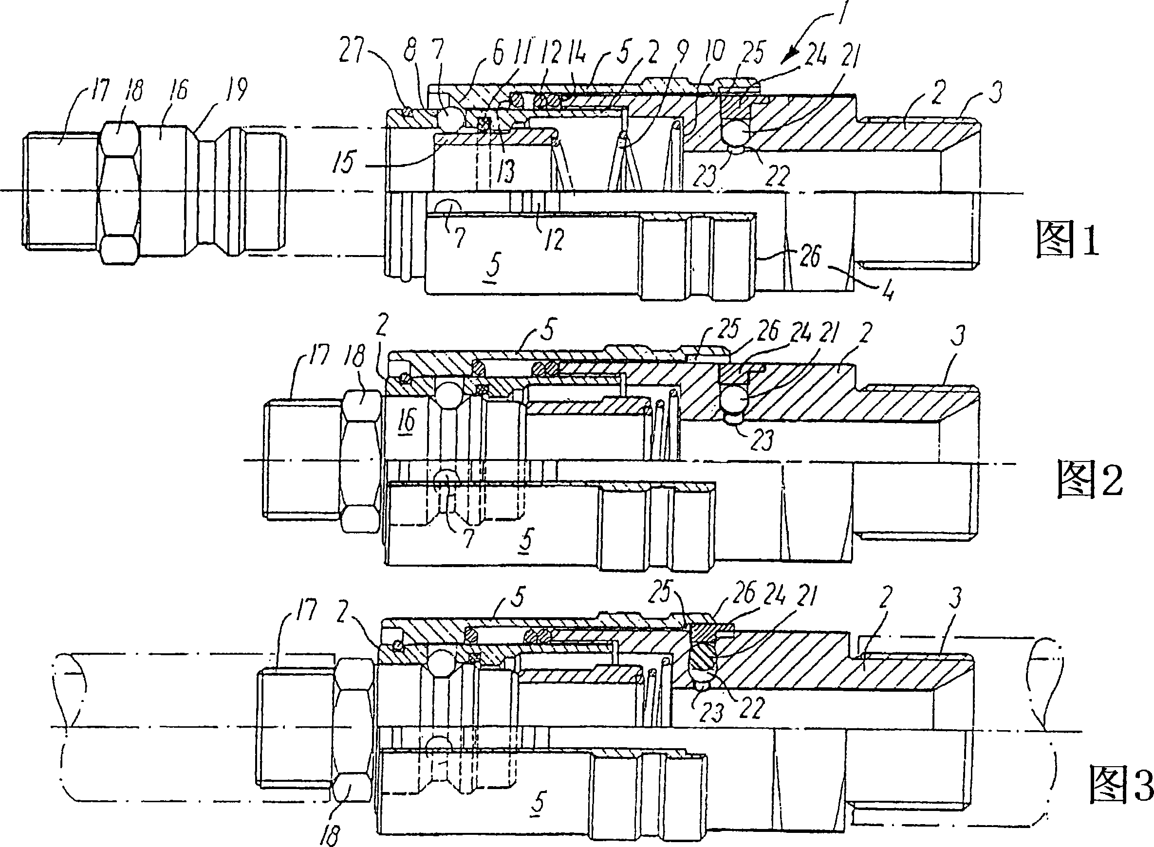
[0027] In FIG. 1 , reference numeral 1 designates a coupling with a connection head 2 having an external thread 3 and an integrated nut 4 . As known, the thread 3 is connected to a pressure supply assembly (not shown).
Login to View More PUM
 Abstract
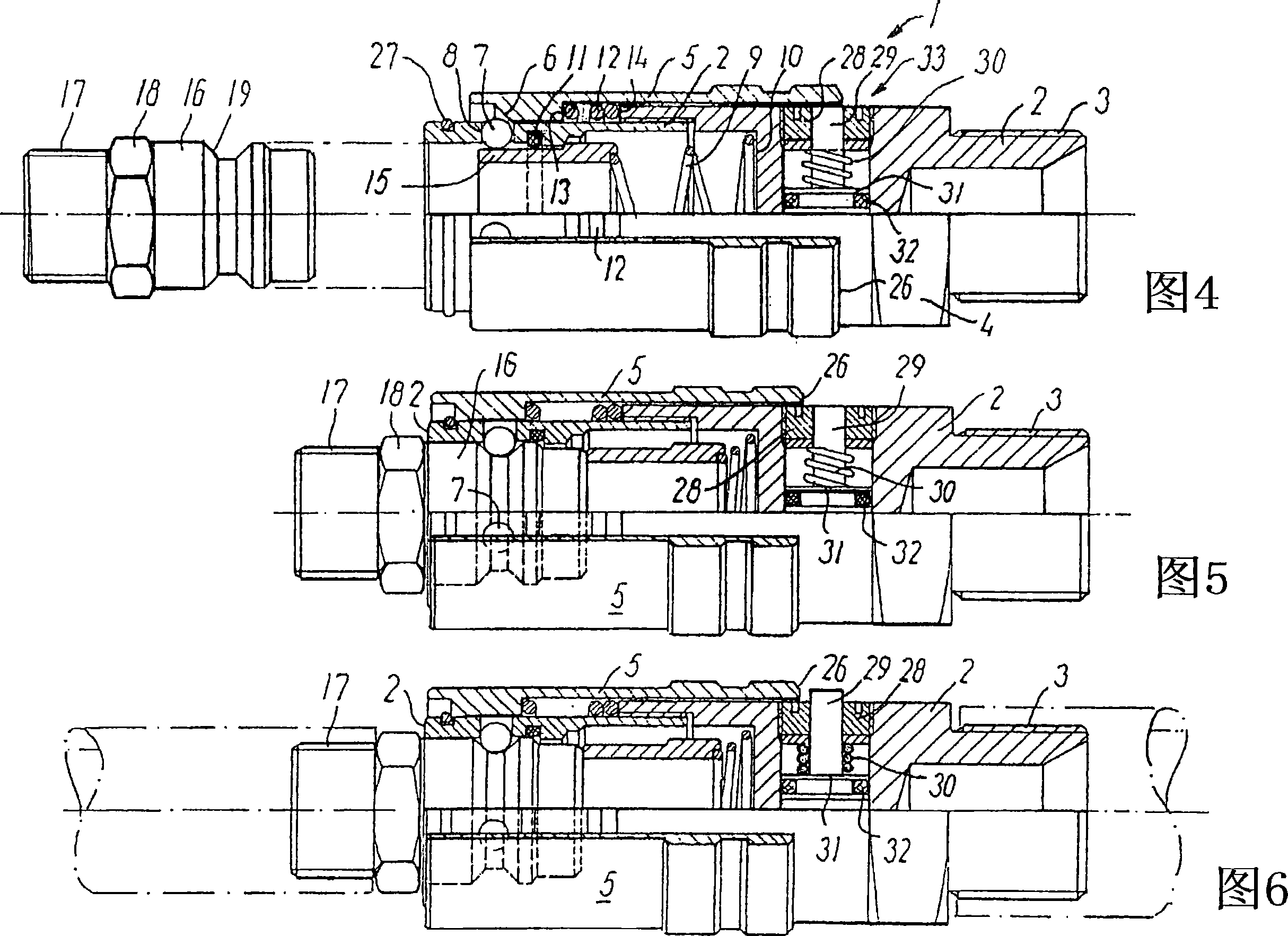
A separable coupling may be formed by a connecting stub (2) and a locking jacket (5) which, when the locking jacket is moved relative to the connecting stub, can lock a nipple (16) in the coupling if fluids under pressure are fed through the coupling, as the connecting stub is provided with a part (21, 29) therein which is movable transversely to the connecting stub, and which, when pressure is applied through the coupling, is pressed partly out of the locking jacket (5) so that movement of the locking jacket is prevented. The movable part may be formed by an O-ring (21), a four-edged ring or the like which can press a split locking ring, concentric with the O-ring, partly out of the connecting stub (2). In an embodiment, the movable part is formed by a bushing (28) with a spring-biased, movable piston (29) which presses the piston (29) out of the bushing (28) and blocks movement of the locking jacket by the action of the fluid which is fed. The bushing (28) has a central through hole in which a spring-biased piston (29) may be moved, such that when pressure is applied through the coupling, the piston protrudes through the hole of the bushing. The invention provides a coupling which ensures that the coupling parts cannot be separated unintentionally from each other, when fluids are fed through the coupling at high pressures and temperatures, which may moreover be chemically aggressive.
Description
technical field [0001] The invention relates to a coupling for the transmission of pressurized fluid, the coupling consisting of a connecting stub and being movable relative to the connecting stub and adapted to lock or release the inner part of the coupling during movement. A locking sleeve for the nipple is formed. Background technique [0002] This type of coupling is used for a variety of purposes, such as for connecting water pipes and faucets. [0003] Another application may be for couplings related to plastic mold cooling, where a fluid is delivered through the coupling causing the temperature of the plastic mold to decrease, for example from 500° to 200°. [0004] A third application is for couplings supplying aggressive chemical liquids or gases. [0005] In the two latter-mentioned cases it is of course desirable that the coupling parts cannot be separated from each other during the supply of fluid. [0006] A coupling with a safety device is known, for example...
Claims
Login to View More Application Information
Patent Timeline
 IPC IPC(8): F16L37/23F16L37/088F16L37/62
CPCF16L37/23Y10T137/87925
Inventor斯特凡·汉森
Owner利达时有限公司