
Edge adaptive image expansion and enhancement system and method

An edge, digital image technology, applied in the field of edge adaptive filtering, can solve problems such as limiting image quality

Inactive Publication Date: 2007-08-29
QUALCOMM INC
View PDF4 Cites 8 Cited by
  • Summary
  • Abstract
  • Description
  • Claims
  • Application Information

AI Technical Summary

Problems solved by technology

These prior art systems do not adapt to specific edge scales and typically use simple bilinear or bicubic interpolation, limiting the quality of the resulting image

Method used


Image

  • Edge adaptive image expansion and enhancement system and method
  • Edge adaptive image expansion and enhancement system and method
  • Edge adaptive image expansion and enhancement system and method

Examples


Embodiment Construction

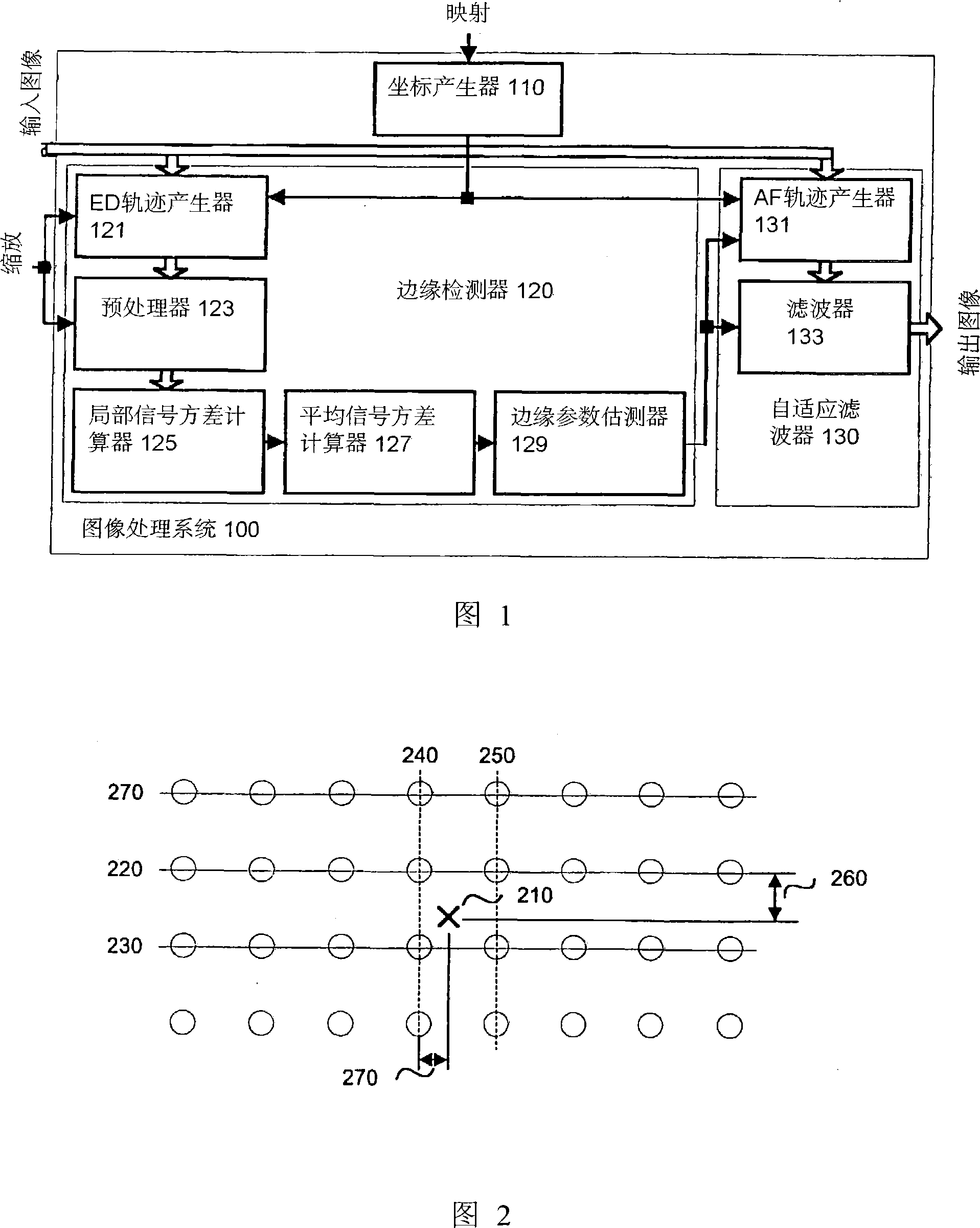
[0046] FIG. 1 is a schematic diagram of an image processing system 100 constructed according to the present invention, which uses edge-adaptive filtering to implement image expansion and enhancement. The image processing system 100 includes a coordinate generator 100 for transforming pixel coordinates from an output image space to an input image space, an edge detection (ED) locus generator for introducing input pixels into edge detection calculations, Preprocessor 123 for pre-filtering and downsampling of the input image, Local Signal Variance Calculator 125 for computing input pixel signal variance, Average Signal Variance Calculator for producing a representation of the signal behavior around the processed output pixel 127. Edge parameter estimator 129 for computing edge parameters, Adaptive Filter (AF) trajectory generator 131 for introducing input pixels into final filtering and filter 133 for computing output pixels.

[0047] In an embodiment of the invention, filtering is...


PUM


Abstract

An edge adaptive system and method for image filtering. The method maps each output pixel onto input image coordinates (110) and then prefilters and resamples the input image pixels around this point to reduce noise and adjust the scale corresponding to a particular operation. Then the edge in the input image is detected based on local (125) and average (127) signal variances in the input pixels. According to the edge detection parameters (129), including orientation, anisotropy and variance strength, the method determines a footprint and frequency response for the interpolation of the output pixel. In a more particular implementation, the method divides the input pixel space into a finite number of directions called skews, and estimates the edge orientation with the nearest skew direction. This further facilitates pixel inclusion in the interpolation of the output pixel.

Description

technical field [0001] The present invention relates to a filtering method for digital image data processing, more specifically, relates to an edge adaptive filtering for digital image data expansion and enhancement. Background technique [0002] A digital image is a 2-dimensional array of digital data where each item represents a pixel of the digital image. Each pixel data has several components such as colors, for example, red, green and blue. The main image processing operation is to expand the image by an arbitrary factor and thereby create a dilated image. Deinterlacing is an example of such an operation, where the video domain is upscaled in the vertical direction using a scaling factor of 1:2. It is well known that when building an upscaled image from a raw image, interpolation between raw digital data arrays is required to obtain a high quality output image. Prior art methods of image expansion interpolate the horizontal and vertical dimensions of the digital imag...

Claims


Application Information

Patent Timeline
IPC IPC(8): G06K9/40
CPCG06T2207/20012G06T2207/10016G06T5/002G06T2207/20021G06T7/0085G06T2207/20192G06T3/403G06T7/13G06T5/70H04N5/208
Inventor 弗拉德米尔·拉奇内格雷戈里·莱昂内尔·史密斯路易·李
Owner QUALCOMM INC
Learn More