Transmission power control unit and transmission power control method

A technology for transmit power control and transmit power, which is applied in power management, electrical components, wireless communication, etc., and can solve problems such as device capability limitations

Inactive Publication Date: 2007-08-29
FUJITSU LTD +1
View PDF1 Cites 7 Cited by
  • Summary
  • Abstract
  • Description
  • Claims
  • Application Information

AI Technical Summary

Problems solved by technology

[0017] Existing techniques are useful in preventing target SIR update delays, but impose limitations on the inherent capabilities of the device, which is not ideal
Moreover, the prior art cannot prevent the target SIR from becoming too small or too large when the transmission power reaches the lower limit or the upper limit.

Method used


Image

  • Transmission power control unit and transmission power control method
  • Transmission power control unit and transmission power control method
  • Transmission power control unit and transmission power control method

Examples


no. 2 Embodiment

[0081] In the first embodiment, the power distribution (Up, Down count) is calculated by comparing the magnitude of the measured SIR and the target SIR, but in the second embodiment, it is calculated based on whether the TPC bit indicates a power increase or a power decrease Power distribution (Up, Down counts). This is because if the measured SIR>target SIR, the TPC bit indicates a power reduction, and if the measured SIR

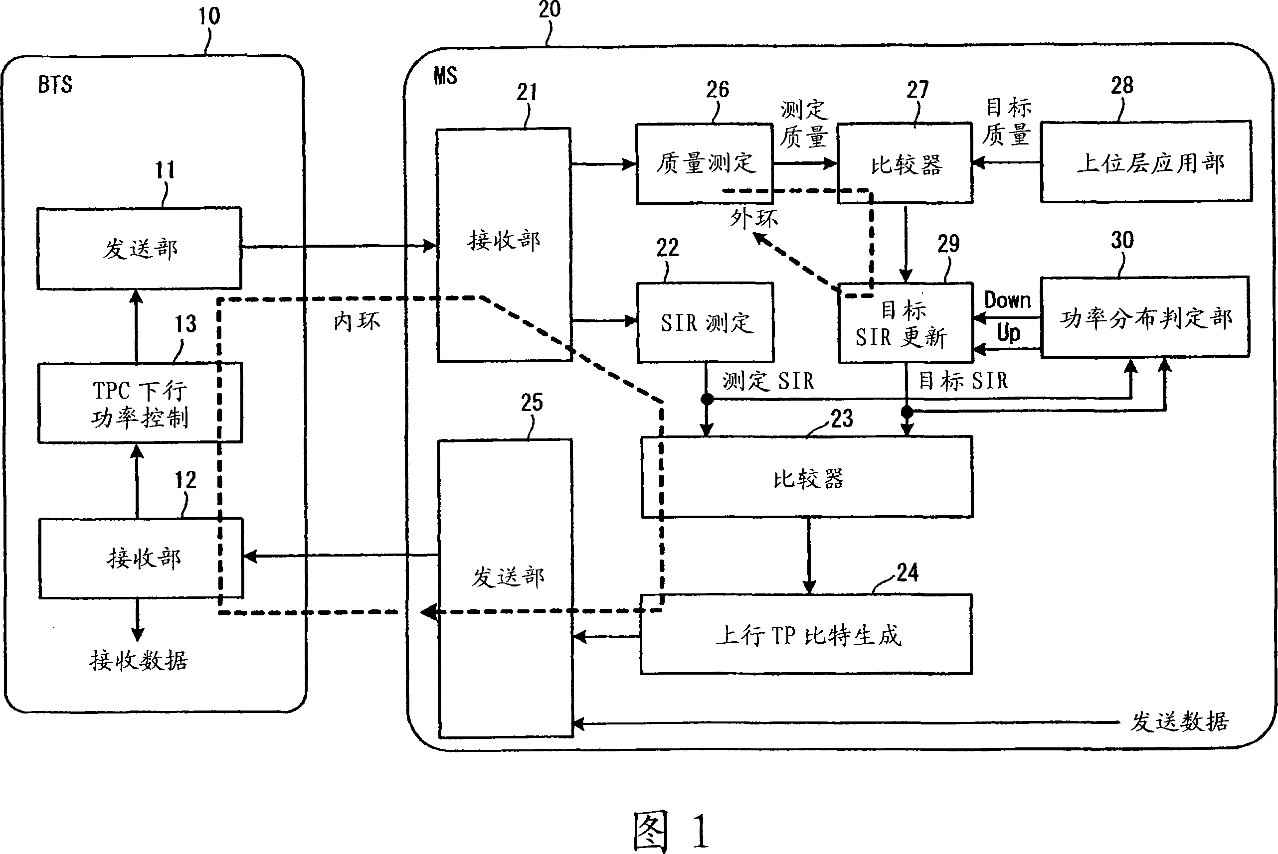
[0082] FIG. 9 is a configuration diagram of a base station and a mobile station for realizing the transmission power control of the second embodiment. The difference from the first embodiment shown in FIG. 1 is that the power distribution determination unit 30 calculates the power distribution (Up , Down counting), and input to comparator 27, others are the same as the first embodiment.

[0083] Fig. 10 is a flow of power distribution measurement processing in the second embodiment. At the beginning, co...


PUM


Abstract

On the receiving side, a measured quality of received data and a target quality are compared and a target SIR is variably controlled. At the same time, the target SIR and a measured SIR are compared, transmission power control information (TPC information) made by based on the comparison results is transmitted to a transmitting side and transmission power is controlled on the transmitting side based on the transmission power control information. Furthermore, whether the transmission power has reached a limit is monitored on the receiving side, and when it reaches the limit, the target SIR is fixed at the latest value not to be revised. When the communication environment changes and transmission power can be controlled, variable control of the target SIR is restarted.

Description

technical field [0001] The present invention relates to a transmission power control device and a transmission power control method, and more particularly to a transmission power control device and a transmission power control method having a structure in which a measured quality of received data (for example, an error quality calculated from decoded data) is compared with a target quality , the target SIR (reception quality target calculated from the received signal before decoding) is variably controlled, and the target SIR is compared with the measured SIR (reception quality calculated from the received signal before decoding), and the transmission is sent to the sending side based on the comparison. The resulting transmission power control information controls the transmission power on the transmission side. Background technique [0002] In W-CDMA mobile communication, the channels are distinguished according to the spreading code assigned to each channel, so that multip...

Claims


Application Information

Patent Timeline
Patent Type & Authority Applications(China)
IPC IPC(8): H04B7/26H04J13/00H04W52/12H04W52/24
CPCH04W52/241H04W52/12
Inventor 中谷内夏彦冨吉德男山埜攻奥村幸彦
Owner FUJITSU LTD
Why Eureka
Try Eureka