Hydraulic-driven cleaner and method for changing hydraulic-jet dynamics and direction

A cleaning machine and cleaning technology, applied in the field of cleaning machines, can solve the problems of increasing the development and production costs of cleaning machines

Active Publication Date: 2007-09-05
COMPUROBOT TECH CO
View PDF2 Cites 8 Cited by
  • Summary
  • Abstract
  • Description
  • Claims
  • Application Information

AI Technical Summary

Problems solved by technology

[0009] For cleaning machines that use gear sets to drive wheels or crawlers, it increases the development and production costs of the cleaning machine, especially to produce and...

Method used


Image

  • Hydraulic-driven cleaner and method for changing hydraulic-jet dynamics and direction
  • Hydraulic-driven cleaner and method for changing hydraulic-jet dynamics and direction
  • Hydraulic-driven cleaner and method for changing hydraulic-jet dynamics and direction

Examples


Embodiment Construction

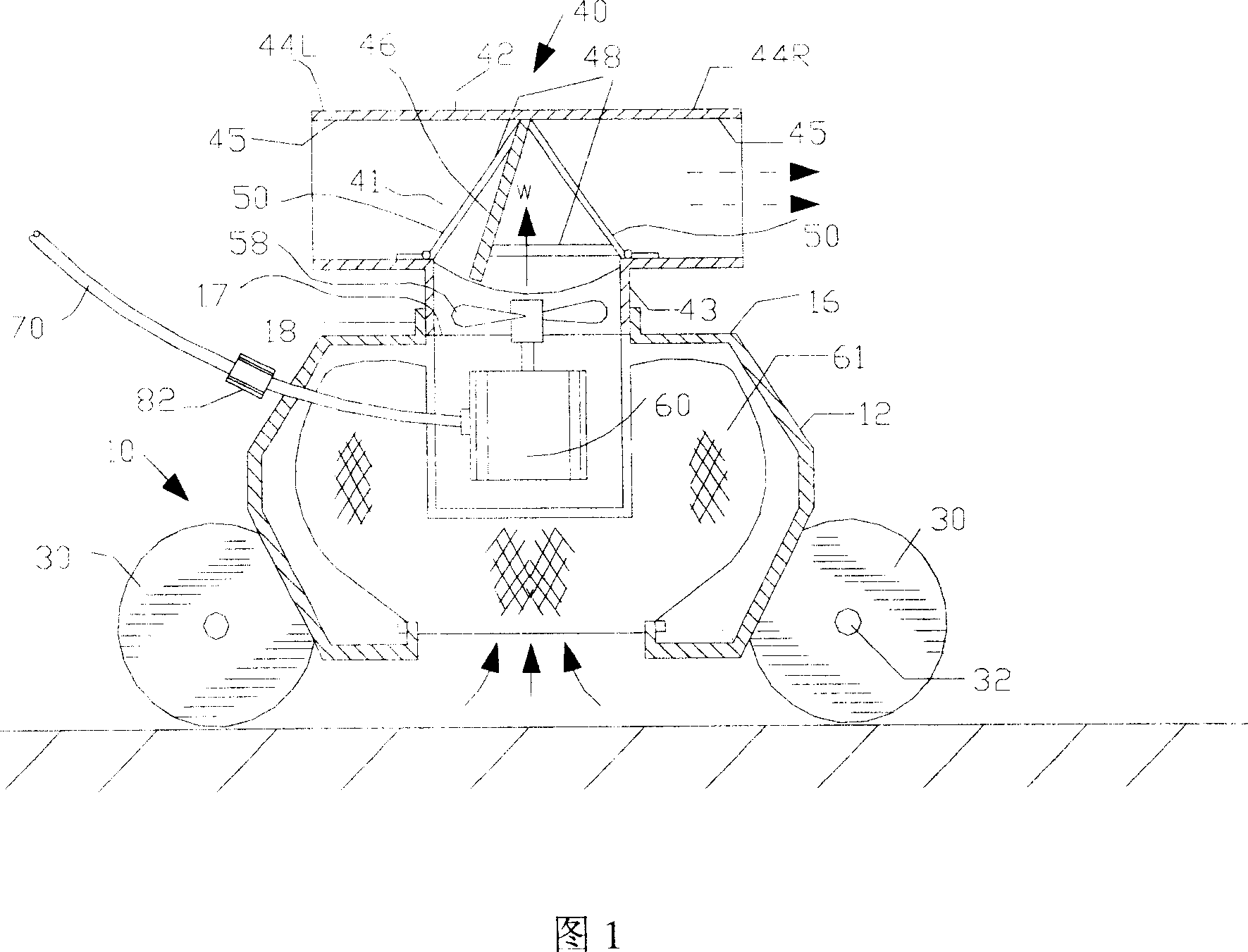
[0071] In the following description, the cleaning machine 10 includes a shell or cover frame 12 and a top cover wall 16, a built-in water pump and a drive motor 60, the water pump sucks pool water and debris in the water enters the cleaning machine through the gap 61 at the bottom of the cleaning machine, and this The notch is surrounded by filter means.

[0072] In the embodiment shown in Figures 1-11, a single motor is used as the pumping and driving means. The drive unit has simple mechanical directional control. In this embodiment, a brief interruption of the electrical current causes the cleaning machine to change direction. Current interruption can be activated using a smart current control switch or a mechanical contact.

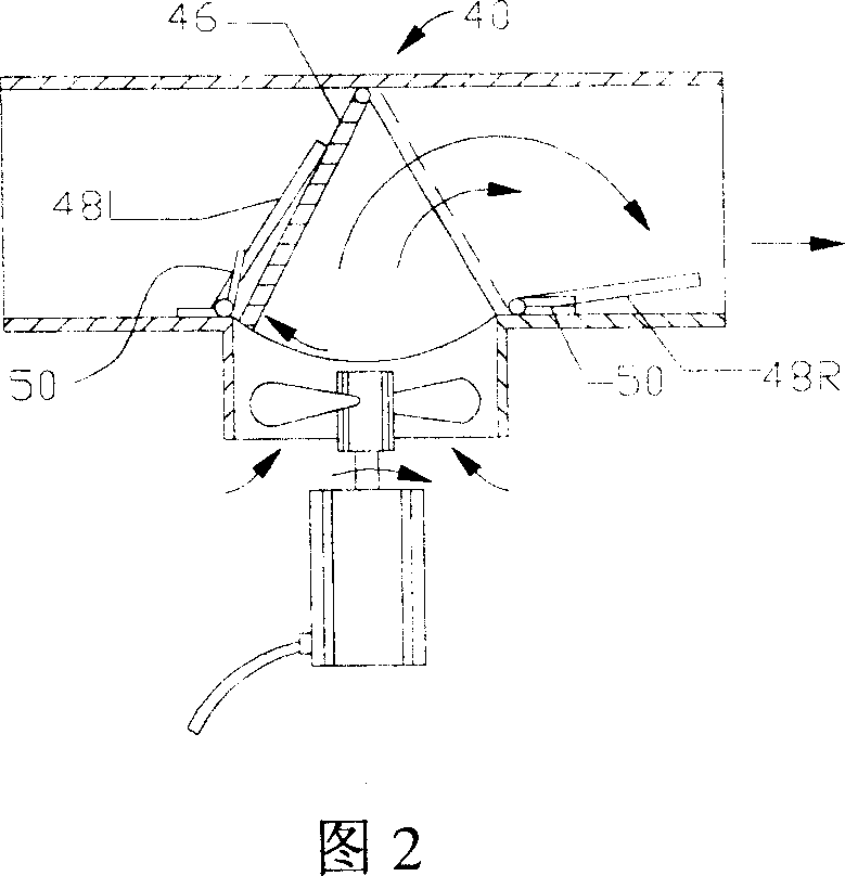
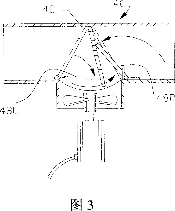
[0073] Figure 1 shows, in partial cross-section, a cleaning machine 10, including a water spray valve assembly 40, mounted on a motor-driven water pump 60, using blades 58 to propel a flow of water 'W' through the bottom of the housing from the bott...


PUM


Abstract

A hydrulically driven cleaner for cleaning flat field has a water pump, a directional water draining pipe, and a water flow controller between the water outlet of water pump and said directional water draining pipe and with two working positions for controlling the direction of spraying water. A method for changing the strength and direction of sprayed water flow is also disclosed.

Description

technical field [0001] The present invention relates to a cleaning machine, in particular to a cleaning machine driven by water and affecting direction; [0002] The invention also relates to a method of varying the force and direction of the water jets of the cleaning machine. Background technique [0003] The existing automatic cleaning machine uses an independent motor to transmit power through a set of gears to a set of wheels or wheel tracks mounted on the shaft to cruise on the surface to be cleaned in the pool. These wheels or tracks are aligned with the longitudinal axis of the cleaning machine Parallel, the direction of the longitudinal axis of the cleaning machine refers to the forward or reverse direction of the cleaning machine. [0004] The cleaning machine disclosed in US Pat. No. 3,979,788 has a matrix composed of three wheels arranged on the triangular points of an isosceles triangle to drive the cleaning machine to completely patrol the bottom of the pool. ...

Claims


Application Information

Patent Timeline
IPC IPC(8): A47L13/26
Inventor 许永健
Owner COMPUROBOT TECH CO
Why Eureka
Try Eureka