
Device and method for controlling glass-board thickness evenness

A technology with uniform thickness and glass plate, which is applied in glass forming, glass forming, glass manufacturing equipment, etc. It can solve the problem of uneven plate thickness and achieve good thermal shock resistance, increased precision, and high thermal conductivity.

Inactive Publication Date: 2010-11-17
HENAN ANCAI HI-TECH +1
View PDF6 Cites 0 Cited by
  • Summary
  • Abstract
  • Description
  • Claims
  • Application Information

AI Technical Summary

Problems solved by technology

[0003] The present invention overcomes the above-mentioned shortcoming of uneven plate thickness, can realize precise temperature control in the width direction of the glass plate, and does not affect the forming of the glass plate, and provides a method of controlling glass in the production process of flat glass by using an overflow down-drawing process. Device and control method for plate thickness uniformity

Method used


Image

  • Device and method for controlling glass-board thickness evenness
  • Device and method for controlling glass-board thickness evenness
  • Device and method for controlling glass-board thickness evenness

Examples


Embodiment 1

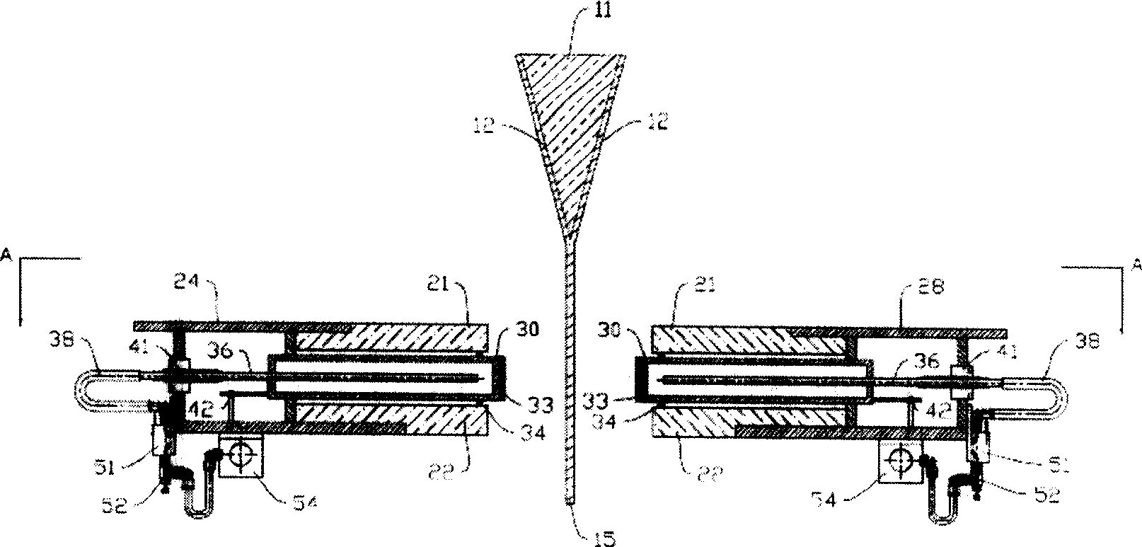
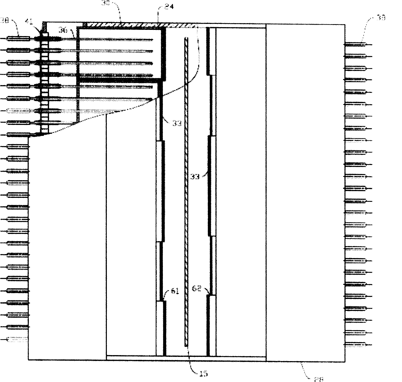
[0032] figure 2 One embodiment of the invention is shown. In this embodiment, the molten glass made according to the glass formula in the patent CN200510007338.0 flows down the overflow brick, and converges at the root of the overflow brick to form a glass plate with a width of 1540 mm and a thickness of 0.7 mm; there are 5 glass plates on each side Closed cavities, their lengths in the width direction of the glass plate are 150mm, 350mm, 600mm, 350mm, 190mm, 10 in total on both sides. The closed cavities of 150mm and 190mm are facing each other, so that the contact between two adjacent closed cavities on both sides of the glass plate will not be facing directly. The cooling pipes in the closed cavity have an inner diameter of 10mm and are arranged at a distance of 60mm. The adjustment distance of each pipe in the direction of the glass plate is 100mm, and the adjustment distance of the pipes in the direction of the width of the glass plate is + / -30mm. There is cooling wate...

Embodiment 2

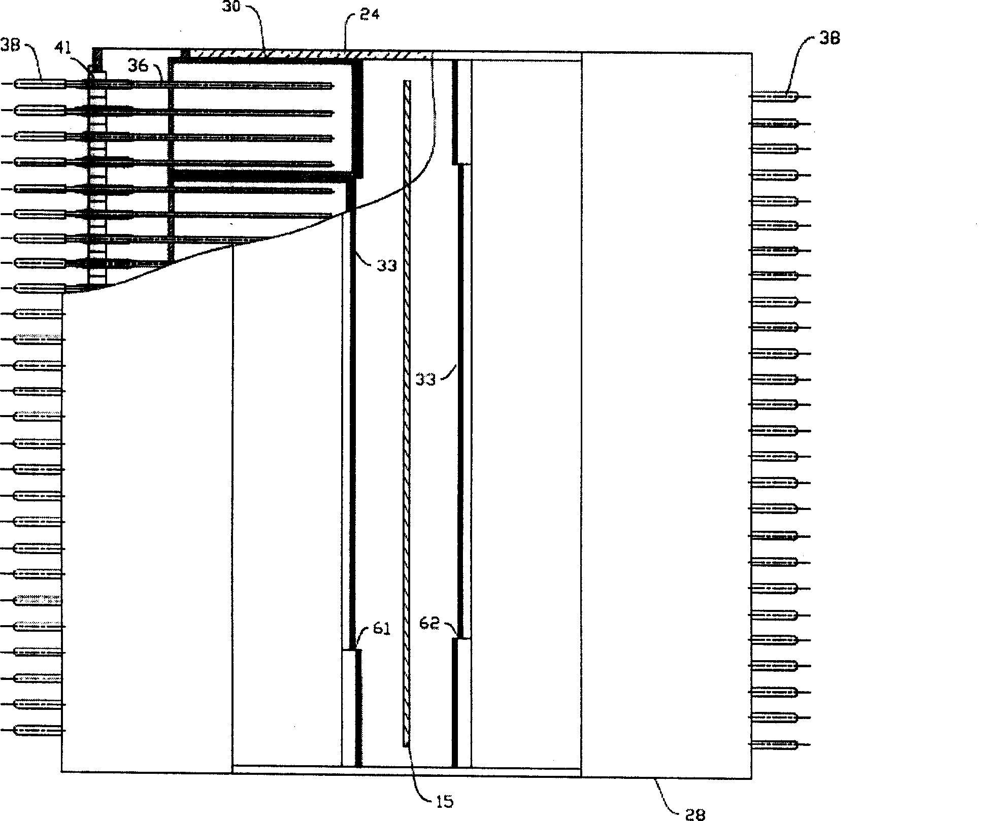
[0034] image 3 Another embodiment of the invention is shown. In this embodiment, the molten glass made according to the glass formula in patent CN200510007338.0 flows down along the overflow brick, and converges at the root of the overflow brick to form a glass plate with a width of 1540mm and a thickness of 0.7mm; there are 3 glass plates on each side Closed cavities, their lengths in the width direction of the glass plate are 150 mm, 1300 mm, and 190 mm respectively, and there are 6 in total on both sides. The closed cavities of 150mm and 190mm are facing each other, so that the contact between two adjacent closed cavities on both sides of the glass plate will not be facing directly. The cooling pipes in the closed cavity have an inner diameter of 10mm and are arranged at a distance of 60mm. The adjustment distance of each pipe in the direction of the glass plate is 100mm, and the adjustment distance of the pipes in the direction of the width of the glass plate is + / -30mm....


PUM


Abstract

An apparatus for controlling the thickness uniformity of glass plate is composed of supporting frame, the upper, lower, left and right insulating refractory brick layers for enclosing whole apparatus, and two closed cavities containing at least one fluid tube and arranged at both sides of glass plate for collecting the heat to heat the fused glass in irradiation mode. Its method features that thedistance between said apparatus and fused glass and the relative position between fused glass and heating element are regulated for controlling the temp of fused glass.

Description

technical field [0001] The invention belongs to the production field of glass used in flat panel displays, and relates to a device and a control method for controlling the thickness uniformity of a glass plate during the production process of flat glass by using an overflow down-drawing process. Background technique [0002] With the continuous advancement of science and technology, flat panel displays have begun to become popular. The flat glass used to display images is one of the key components of flat panel displays, and its quality directly affects the display quality of display devices. For example, in liquid crystal displays , especially for thin-film transistor display (TFT / LCD) glass, in the process of manufacturing such a display screen, various circuit patterns and thin-film transistors need to be formed on the surface of the glass. The formation of these patterns and devices is based on the use of The method similar to forming large-scale integrated circuits is f...

Claims


Application Information

Patent Timeline
Patent Type & Authority Patents(China)
IPC IPC(8): C03B17/06
CPCC03B17/067
Inventor 贾伟李震兰陟万志刚
Owner HENAN ANCAI HI-TECH
Learn More