Supercharge Your Innovation With Domain-Expert AI Agents!

Connector for discharging tube, discharging tube with connector and surface light source device

A technology for connectors and discharge tubes, which is applied in the fields of connectors for discharge tubes, discharge tubes, and surface light source devices, and can solve problems such as glass tubes are prone to cracks, connectors move, and are applied to connectors.

Inactive Publication Date: 2007-09-05
SANKEN ELECTRIC CO LTD
View PDF3 Cites 3 Cited by
  • Summary
  • Abstract
  • Description
  • Claims
  • Application Information

AI Technical Summary

Problems solved by technology

[0009] However, as described above, when the discharge tube is mounted on the holder, once the connector provided at the end of the glass tube is fitted into the fitting part of the electrode holding part, an external force will be applied to the connector. will move from the glass tube
Especially, in the case where a gap is formed between the connector and the glass tube, the connector is easily moved from the glass tube
In this way, once the connector is moved from the glass tube, stress will be applied to the lead wire of the discharge tube, and cracks will easily occur on the glass tube

Method used


Image

  • Connector for discharging tube, discharging tube with connector and surface light source device
  • Connector for discharging tube, discharging tube with connector and surface light source device
  • Connector for discharging tube, discharging tube with connector and surface light source device

Examples


Embodiment Construction

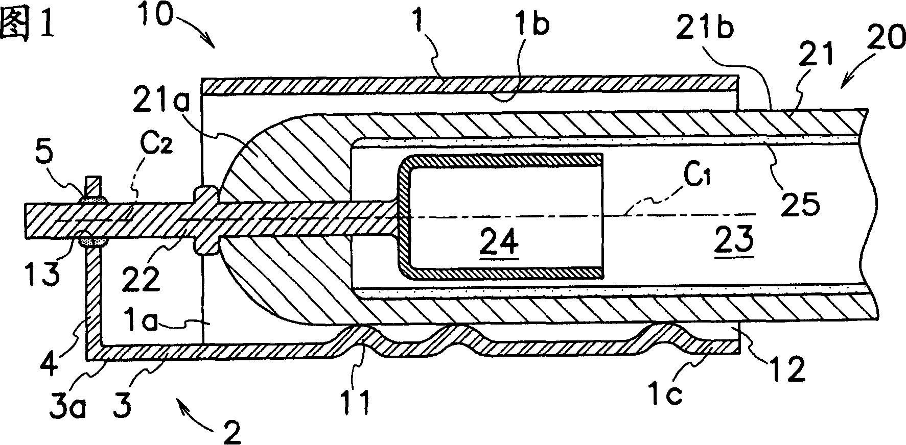
[0039] Embodiments of a connector for a discharge tube, a discharge tube with a connector, and a surface light source device according to the present invention for use in a cold cathode fluorescent discharge tube used in a backlight of a display device will be described with reference to FIGS. 1 to 25 . The discharge tube (20) shown in the above drawings is the same as the discharge tube shown in Fig. 26, and the same reference numerals are used, and description thereof will be omitted.

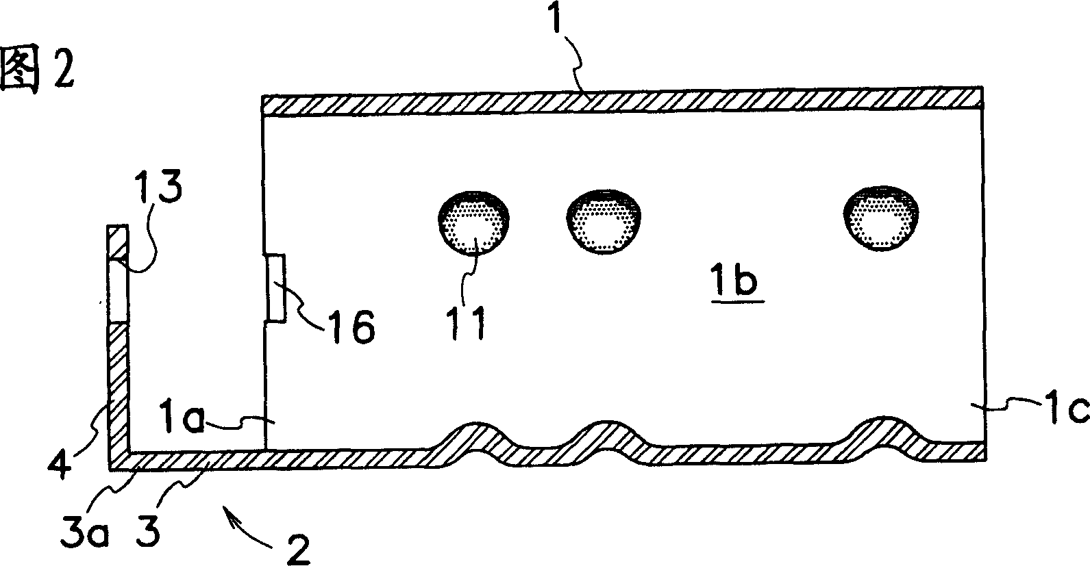
[0040]As shown in Figure 1, the discharge tube connector of the present invention has a cylindrical body (1), a strip-shaped lead-out portion (3) extending from one end (1a) of the cylindrical body (1) to the axial direction outside of the cylindrical body (1) And the protruding part (4) formed by bending from the front end (3a) of the lead-out part (3). The cylinder body (1), the lead-out part (3) and the protrusion part (4) are integrally formed of metal with good elasticity such as phospho...


PUM


Abstract

The invention provides a metal connector for discharge tubes, capable of easing up stress transferred from connector for discharge tubes to leading line and preventing crashing between the leading line and glass tube. The connector for discharge tubes comprises a tunnel body (1), zonal export part (3) extending from one end of tunnel body (1) to lateral of tunnel body (1) at axis direction, jut (4) bending formed from the front end (3a) of the export part (3). When the tunnel body (1) is mounted on the end (21a)of the glass tube (21) forming discharge tube, leading line (22) extending from end (21a)of the glass tube (21)is installed in the through hole or notch (13) of the jut (4). The zonal and resilient export part (3) and jut (4)subjected by the stress of the tunnel body (1) easily disform and the stress transferred from connector for discharge tubes can be eased up.

Description

technical field [0001] The present invention relates to a discharge tube connector attached to an end portion of a glass tube constituting a discharge tube, a discharge tube with a connector having the discharge tube connector, and a surface light source device. Background technique [0002] Discharge tubes (cold cathode fluorescent tubes or CCFLs) are used as liquid crystal backlight sources for display devices such as television monitors, notebook computers, or mobile phones. As shown in FIG. 26 , a well-known discharge tube (20) has a glass tube (21), a pair of metal electrodes (24), a metal lead (リド) (22) and a phosphor layer (25), A glass tube (21) forms a closed space (23) for storing discharge gases such as argon and mercury; a pair of metal electrodes (24) are cup-shaped and placed in the closed space (23); metal lead wires (22 ) is connected to the electrode (24) and the other end is exported from the end (21a) of the glass tube (21); The ultraviolet rays generate...

Claims


Application Information

Patent Timeline
Patent Type & Authority Applications(China)
IPC IPC(8): H01R33/00H01J5/50F21V19/00G02F1/13357G02F1/1335
Inventor 森裕一田仲晋作
Owner SANKEN ELECTRIC CO LTD
Features
  • R&D
  • Intellectual Property
  • Life Sciences
  • Materials
  • Tech Scout
  • Unparalleled Data Quality
  • Higher Quality Content
  • 60% Fewer Hallucinations
Learn More