
Apparatus for automatically compensating for clearance of support yoke in rack-and-pinion steering system

A technology of steering system and automatic compensation, which is applied in the direction of transmission, friction transmission, transmission parts, etc.

Active Publication Date: 2007-09-12
HL MANDO CORP +1
View PDF0 Cites 28 Cited by
  • Summary
  • Abstract
  • Description
  • Claims
  • Application Information

AI Technical Summary

Problems solved by technology

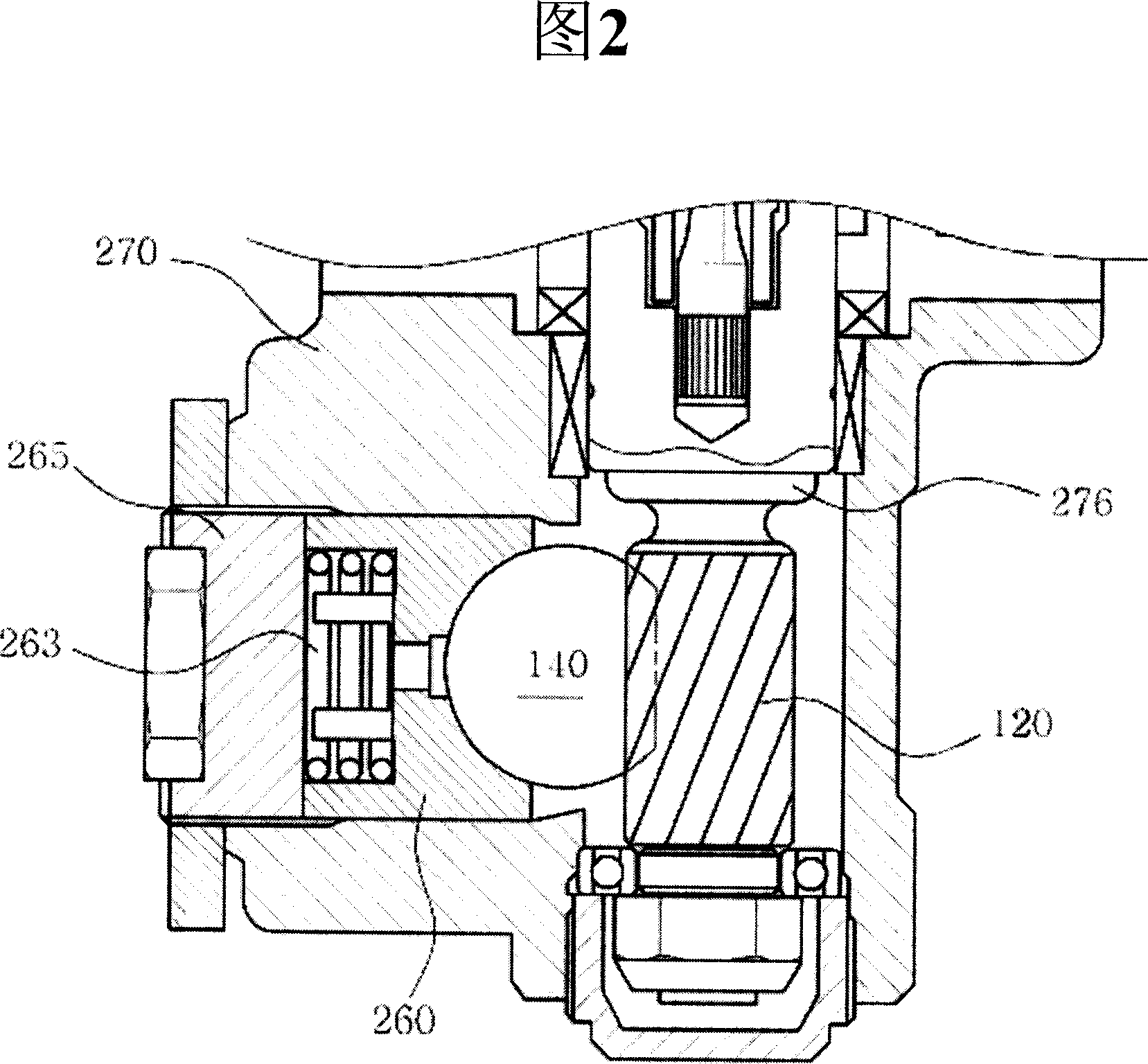
[0017] In order to avoid this noise due to vibration, the yoke plug 265 must be readjusted manually, and during repairs, the entire steering system often has to be replaced

Method used


Image

  • Apparatus for automatically compensating for clearance of support yoke in rack-and-pinion steering system
  • Apparatus for automatically compensating for clearance of support yoke in rack-and-pinion steering system
  • Apparatus for automatically compensating for clearance of support yoke in rack-and-pinion steering system

Examples


Embodiment Construction

[0025] Hereinafter, preferred embodiments of the present invention will be described with reference to the accompanying drawings. In the following description and drawings, the same reference numerals are used to denote the same or similar components, and thus repeated descriptions of the same or similar components will be omitted.

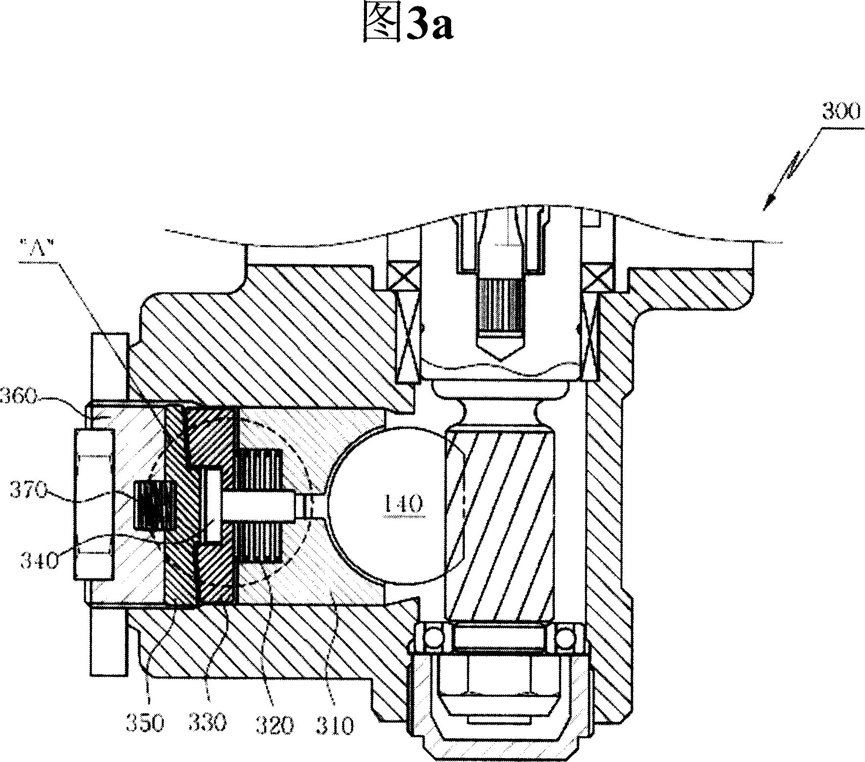
[0026] Fig. 3a is a cross-sectional view of the device for automatically compensating the clearance of a support yoke according to a preferred embodiment of the present invention, and Fig. 3b partially enlarges part A shown in Fig. 3a.

[0027] The device 300 for automatically compensating the backlash of a support yoke according to a preferred embodiment of the present invention includes: a support yoke 310; a yoke spring 320; a first cam 330; a fixing element 340; a second cam 350; Torsion spring 370.

[0028] The yoke plug 360 has the same material and shape as a conventional yoke plug except for a fixing recess 315 formed therein for mounting...


PUM


Abstract

Disclosed is an apparatus (300) for automatically compensating for the clearance of a support yoke (310) in a rack-and-pinion steering system by using a torsion spring (370) and a cam mechanism so that, when the support yoke (310) generates a clearance, it is automatically compensated for without separate adjustment. Unlike conventional apparatuses for reducing rattle noise resulting from the increased gap between the yoke plug (360) and the support yoke (310), the disclosed apparatus maintains a constant gap. In addition, the first cam (330), the second cam (350), and the torque spring (370) automatically compensate for the clearance of the support yoke (310).

Description

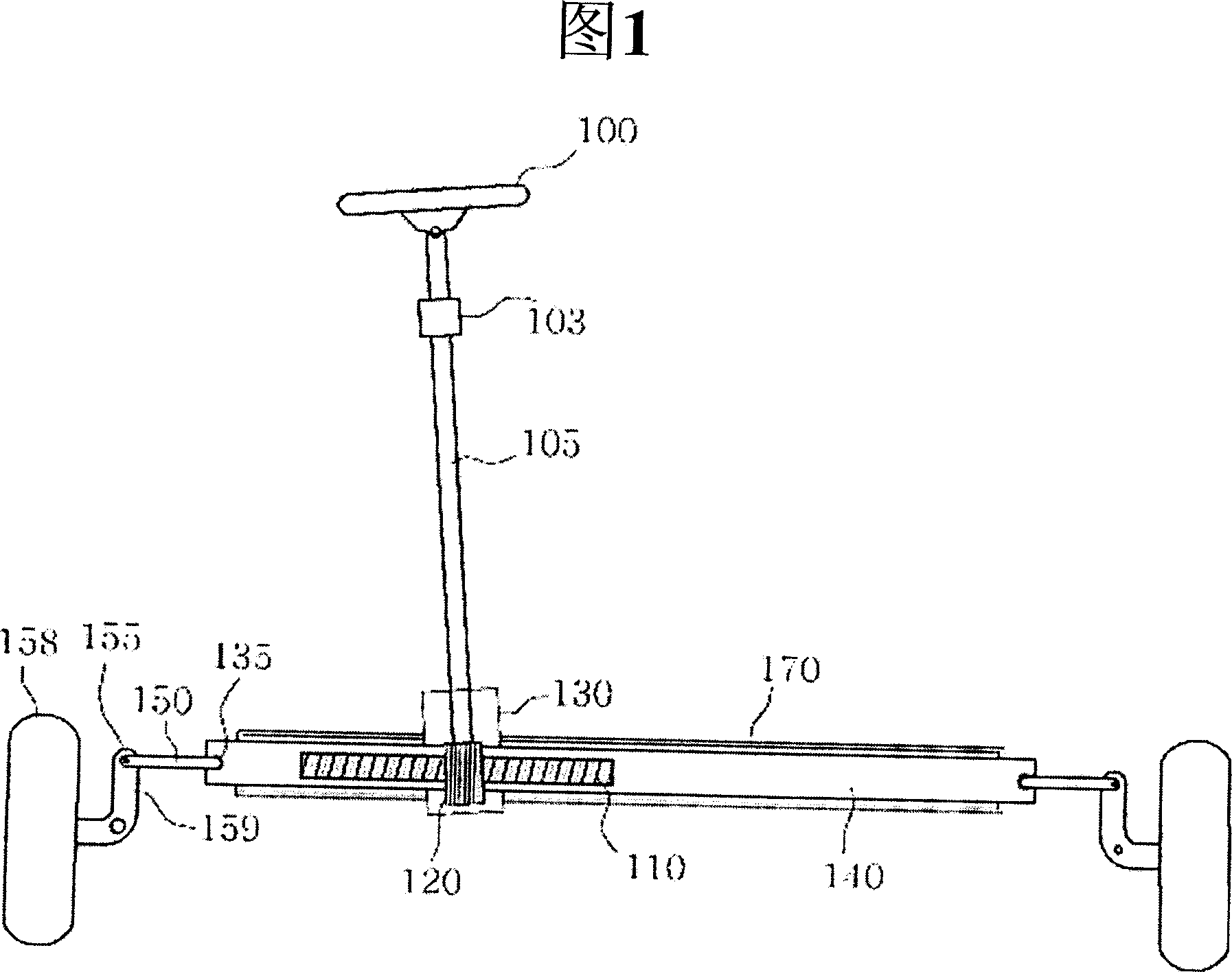
field of invention [0001] The invention relates to a device for automatic compensation of backlash in a support yoke in a rack-and-pinion steering system. More particularly, the present invention relates to a device for automatically compensating for backlash of a support yoke in a rack-and-pinion steering system by utilizing a torsion spring and cam mechanism so that when the support yoke develops play, Automatic compensation without individual adjustments. Background of the invention [0002] Generally known in the art, steering systems enable a driver to steer his / her vehicle in a desired direction by changing the center of rotation of the front wheels. [0003] Figure 1 shows the main structure of a conventional automobile steering system. [0004] Referring to Fig. 1, this conventional steering system includes: a steering wheel 100 arranged in the passenger compartment; a steering shaft 105 connected to the steering wheel 100; a steering column 103 for fixing the stee...

Claims


Application Information

Patent Timeline
Patent Type & Authority Applications(China)
IPC IPC(8): B62D3/12F16H57/12
CPCY10T74/19623F16H55/283B62D3/123F16H19/04F16H57/02B60Y2306/09
Inventor 宋浚圭曹希权
Owner HL MANDO CORP
Learn More