
Discrete high switching rate illumination geometry structure for single imager microdisplay

A technology of imager and display device, applied in the field of projection system, can solve the problems of expensive color wheel, adverse effect of light transmission efficiency, poor power efficiency, etc.

Inactive Publication Date: 2007-09-12
INTERDIGITAL CE PATENT HLDG
View PDF2 Cites 4 Cited by
  • Summary
  • Abstract
  • Description
  • Claims
  • Application Information

AI Technical Summary

Problems solved by technology

A color wheel for separating light in time would also be expensive
In addition, the efficiency of light transmission is adversely affected when the beam is on the spokes that separate the different color filters of the color wheel
Single imager microdisplay projection systems also offer poor power efficiency because most of the light produced at any given time is filtered out by the color wheel

Method used


Image

  • Discrete high switching rate illumination geometry structure for single imager microdisplay
  • Discrete high switching rate illumination geometry structure for single imager microdisplay

Examples


Embodiment Construction

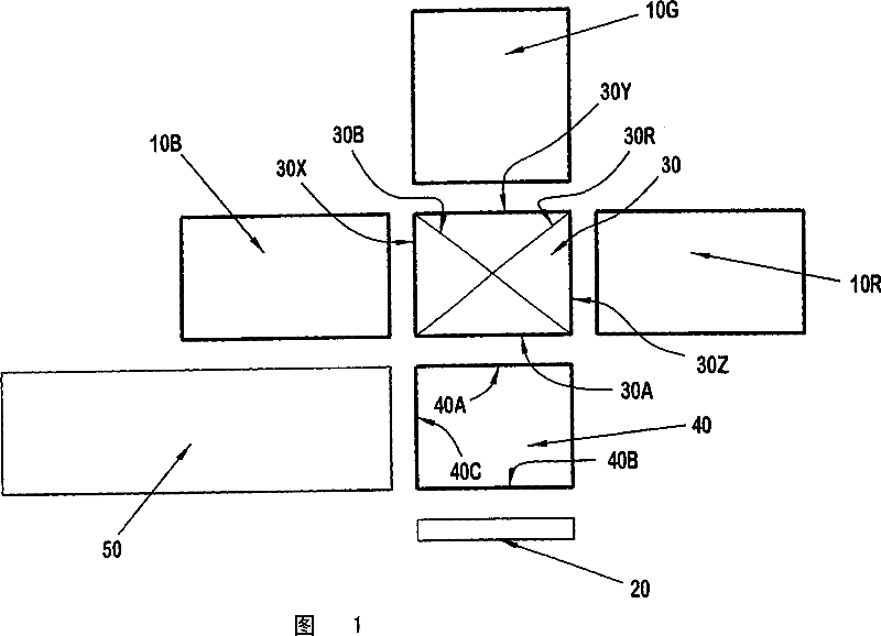
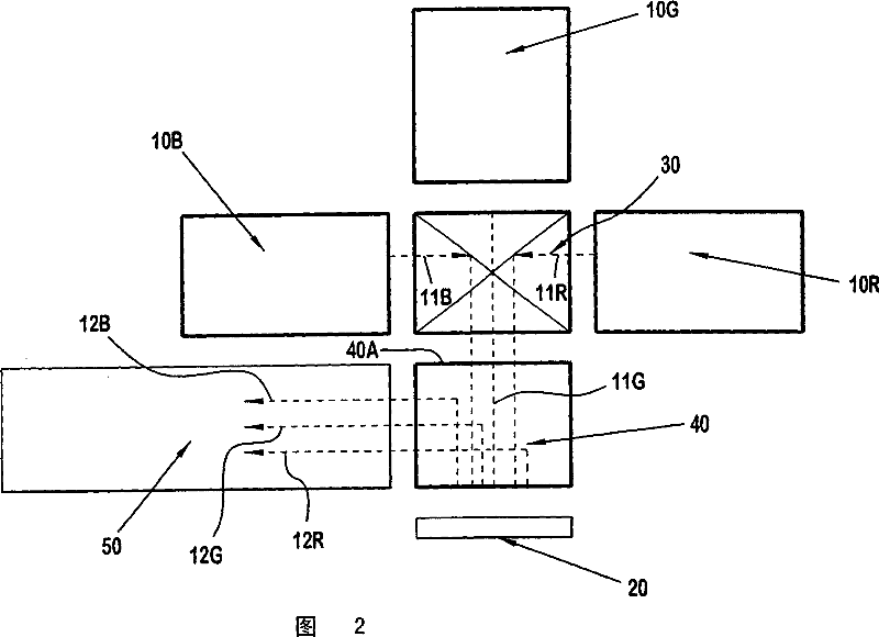
[0009] 1 and 2 illustrate projection systems according to exemplary embodiments of the present invention. Three monochromatic light sources 10B, 10G and 10R emit monochromatic light beams 11B, 11G and 11R in the blue, green and red spectrums, respectively. In the illustrated example, the monochromatic light sources 10B, 10G, 10R are resonant microcavity structure (RMA) devices. These monochromatic light sources 10B, 10G and 10R are sequentially turned on so that at any point in time, only one of the three monochromatic light sources is turned on. Thus, although all three monochromatic beams 11B, 11G, 11R are shown for convenience in Figure 2, only one of these three beams will be produced at any particular time. These monochromatic light sources 10B, 10G, 10R have high switching speeds so that they can each be cycled on during a single refresh cycle for displays employing typical projection systems. For example, a typical LCD or DLP display TV with UHP lamps and using sequen...


PUM


Abstract

A projection system is provided, comprising three discrete monochromatic light sources for sequentially providing monochromatic beams of blue, green and red light to a single imager, which modulates the light on a pixel-by-pixel basis to form a matrix of modulated light pixels. Each of the monochromatic light sources has a switching rate consistent with a refresh rate of the projection system for generating sequential, discrete monochromatic beams of light. The monochromatic matrices of modulated light are combined to form a full color viewable image.

Description

technical field [0001] The present invention relates to a projection system, and more particularly to a projection system utilizing a discrete monochromatic high switching speed light source with a single imager microdisplay. Background technique [0002] Microdisplays are increasingly used to project images in display applications such as rear projection televisions. For color projection systems, one or more imagers of the microdisplay modulate a monochromatic light input on a pixel-by-pixel basis to form a matrix of modulated light pixels. The three matrices of monochromatic modulated light are then combined on a screen or diffuser to form a viewable color image. This monochromatic imaging can be achieved by splitting a white light source into three monochromatic beams and using three separate imagers to modulate the separate monochromatic beams (known as a multi-imager microdisplay). However, using three separate imagers in a microdisplay projection system can be expens...

Claims


Application Information

Patent Timeline
Patent Type & Authority Applications(China)
IPC IPC(8): H04N9/31
CPCH04N9/3197H04N9/3108H04N9/3164H04N5/74H04N9/31
Inventor E·T·小哈尔J·E·利斯特E·M·奥唐奈尔
Owner INTERDIGITAL CE PATENT HLDG
Learn More