Voltage regulator and method having reduced wakeup-time and increased power efficiency

a voltage regulator and wakeup time technology, applied in the direction of electric variable regulation, process and machine control, instruments, etc., can solve the problems of wasting power used to charge the compensation capacitor each time the regulator is pressed, reducing power consumption, and reducing the time it takes to charge the compensation capacitor

Inactive Publication Date: 2011-09-27
MONTEREY RES LLC
View PDF8 Cites 16 Cited by
  • Summary
  • Abstract
  • Description
  • Claims
  • Application Information

AI Technical Summary

Benefits of technology

[0012]The present invention provides a solution to these and other problems, and offers further advantages over conventional voltage regulators and methods of operating the same.

Problems solved by technology

Thus, reducing power consumption is an extremely important issue, as consumers increasingly demand longer operating times between recharging.
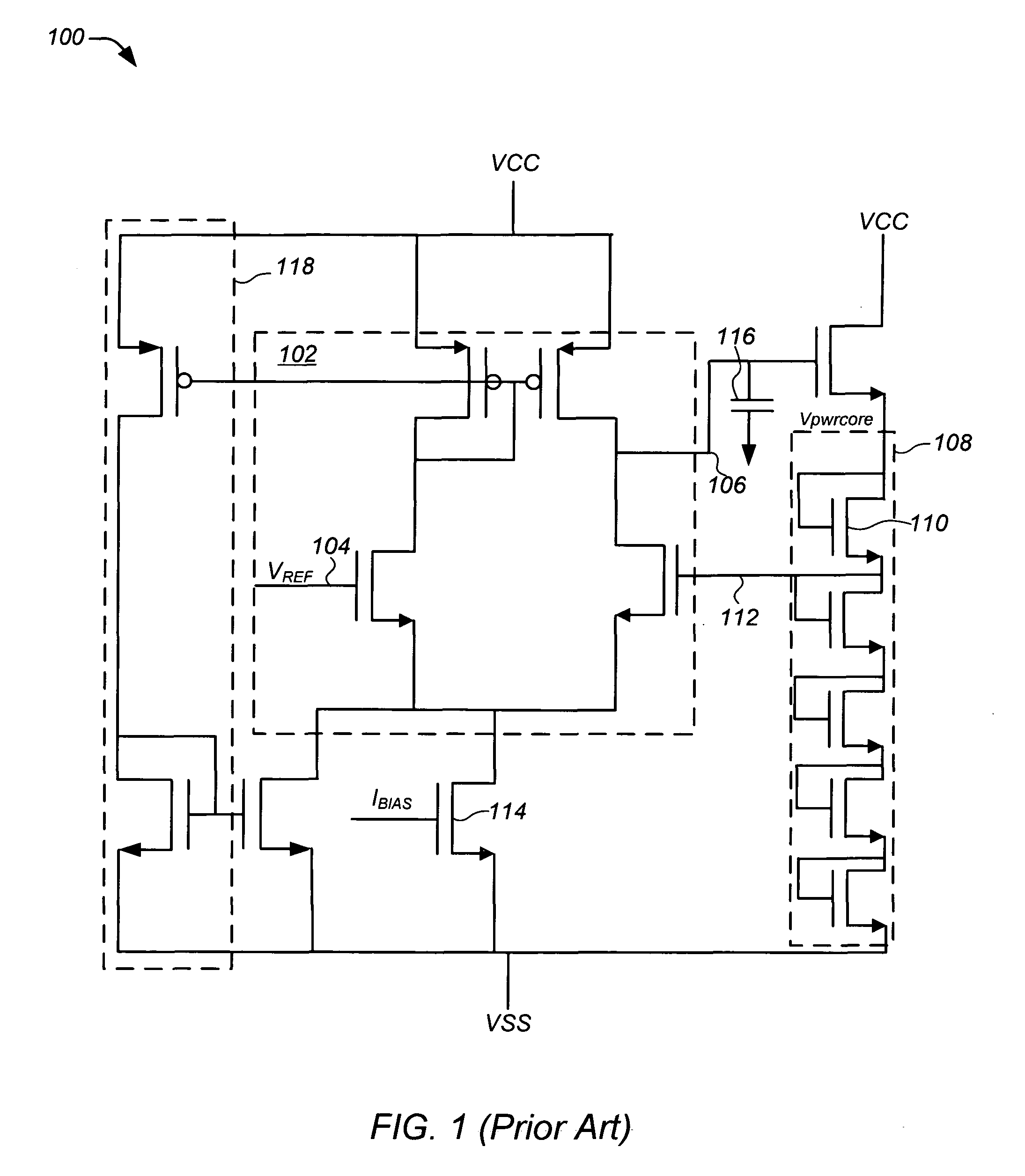
Thus, one problem with conventional active voltage regulators 100 is the time it takes to charge this compensation capacitor 116, which accounts for the greater part of the wake-up time.
Another problem with conventional active voltage regulators 100 including a compensation capacitor 116, such as that shown in FIG. 1, is that the power used to charge the compensation capacitor is wasted each time the regulator toggles between standby and active mode.
Although the adaptive biasing stack 118 can improve wake-up time it does not solve the problem with wasting of power used to charge the compensation capacitor 116.
In addition, adaptive biasing introduces a number of drawbacks or disadvantages including design complexity, overshooting on the output voltage, and the need for extra verification and / or mismatch concerns for the transistors in the adaptive biasing stack, which can result in either instability or increased quiescent current.
Moreover, adaptive biasing does not work in headroom limited designs, such as pumped NGATE designs in which a first stage of the OPAMP operates on the pump as the adaptive biasing current needs to be controlled to prevent collapse of pump.

Method used


Image

  • Voltage regulator and method having reduced wakeup-time and increased power efficiency
  • Voltage regulator and method having reduced wakeup-time and increased power efficiency
  • Voltage regulator and method having reduced wakeup-time and increased power efficiency

Examples


Embodiment Construction

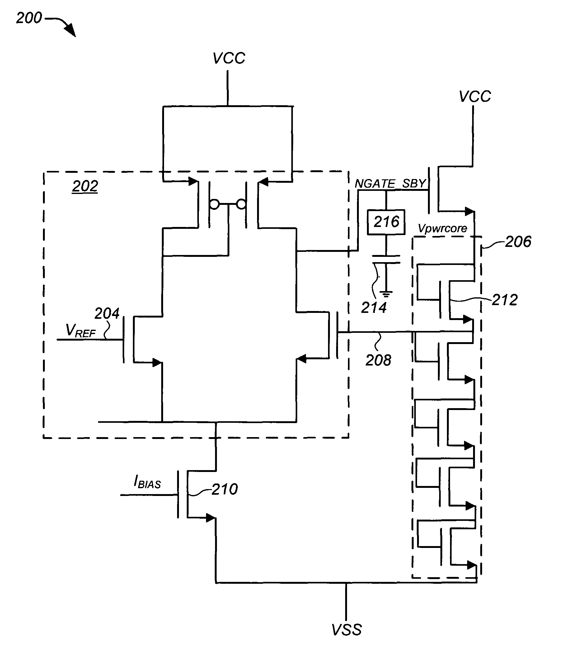
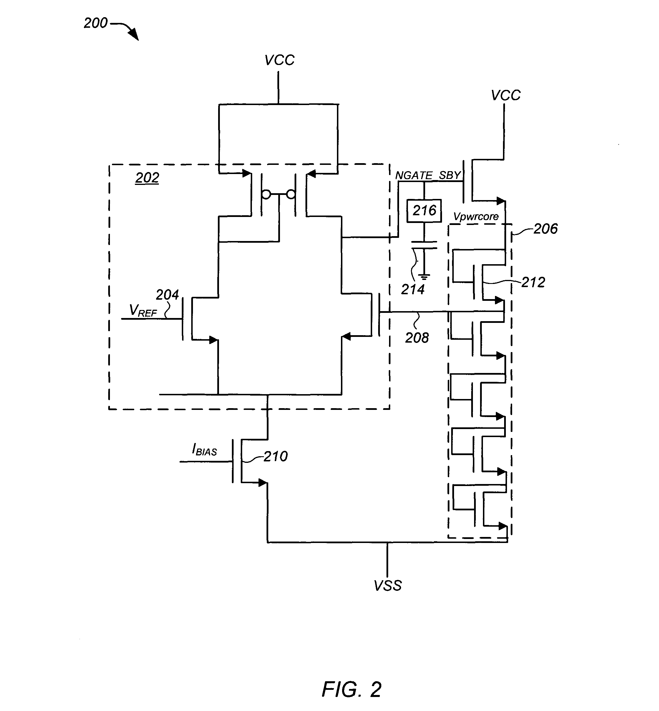
[0023]The present invention is directed to voltage regulating circuits or regulators and methods of using the same that improve wakeup-time and reduce power consumption in switching a device from standby or sleep-mode to active mode.

[0024]The voltage regulator and method of the present invention are particularly useful in mobile or portable devices, such as in cellular telephones, portable digital assistants (PDAs), laptops, and other like devices, that include distributed shared memory (DSM) on a single-chip and in which on-chip voltage regulators are used.

[0025]In the following description, for purposes of explanation, numerous specific details are set forth in order to provide a thorough understanding of the present invention. It will be evident, however, to one skilled in the art that the present invention may be practiced without these specific details. In other instances, well-known structures, and techniques are not shown in detail or are shown in block diagram form in order ...


PUM


Abstract

A voltage regulator and method of using the same are provided that improve wakeup-time and reduce power wastage in switching a device from standby or sleep-mode to active mode. Generally, the voltage regulator includes: (i) a standby regulator having a high-impedance node (NGATE); (ii) an active regulator having a high-impedance node (dominant pole node); (iii) a compensation capacitor; and (iv) a switching circuit to couple the compensation capacitor to the high-impedance node (NGATE) of the standby regulator while the device is in sleep-mode to pre-charge the compensation capacitor, and to couple the compensation capacitor to the high-impedance node (dominant pole node) of the active regulator while the device is in active or non-sleep-mode. Other embodiments are also disclosed.

Description

CROSS-REFERENCE TO RELATED APPLICATIONS[0001]The present application claims the benefit of priority under 35 U.S.C. 119(e) to U.S. Provisional Patent Application Ser. No. 60 / 873,803, entitled “A Voltage Regulator And Method Having Improved Wakeup-Time And Power Efficiency,” filed Dec. 8, 2006, which application is hereby incorporated by reference in its entirety.TECHNICAL FIELD[0002]The present invention relates generally to reducing power consumption in electronic devices, and more particularly to voltage regulators and methods of using the same to reduce wakeup-time and power consumption in switching a voltage regulator from standby or sleep-mode to active mode.BACKGROUND OF THE INVENTION[0003]Many mobile or portable electronic devices, such as cellular telephones, portable digital assistants or PDAs, laptops, and other like devices, which operate on battery power. Thus, reducing power consumption is an extremely important issue, as consumers increasingly demand longer operating t...

Claims


Application Information

Patent Timeline
Patent Type & Authority Patents(United States)
IPC IPC(8): G05F1/565
CPCG05F1/575
Inventor DAMARAJU, NAGA RADHA KRISHNATIYYAGURA, SRIKANTH REDDY
Owner MONTEREY RES LLC
Why Eureka
Try Eureka