Receiver device, communications device, wireless LAN device, power control method for a receiver device, power control program for a receiver device, and storage medium

a technology for receiver devices and power control methods, applied in the direction of gain control, high-level techniques, pulse techniques, etc., can solve the problem of power waste that cannot be ignored, and achieve the effect of saving power

Inactive Publication Date: 2006-01-05
SHARP KK
View PDF3 Cites 14 Cited by
  • Summary
  • Abstract
  • Description
  • Claims
  • Application Information

AI Technical Summary

Benefits of technology

[0012] The present invention, in view of these problems, has an objective to provide a receiver device (for example, wireless LAN device) capable of power savings.

Problems solved by technology

This waste of power cannot be ignored, especially, when the wireless LAN device is mounted to a mobile terminal.

Method used


Image

  • Receiver device, communications device, wireless LAN device, power control method for a receiver device, power control program for a receiver device, and storage medium
  • Receiver device, communications device, wireless LAN device, power control method for a receiver device, power control program for a receiver device, and storage medium
  • Receiver device, communications device, wireless LAN device, power control method for a receiver device, power control program for a receiver device, and storage medium

Examples


embodiment 1

[0036] Referring to FIGS. 3, 4, the following will describe another embodiment in accordance with the wireless LAN terminal (receiver device, wireless LAN device) of the present invention.

[0037] As shown in the figures, a receiver section 102 in a wireless LAN terminal 101 in accordance with the present embodiment has a direct conversion structure composed chiefly of a radio frequency signal processor section (first signal processor section) 104, a signal detector section 106, a gain regulator section (second signal processor section) 105, a digital demodulator section (demodulator section) 107, a gain control section 108, and an operation state control section 109.

[0038] The radio frequency signal processor section 104, the gain regulator section 105, and a part of the signal detector section 106 (RSSI circuit 131) make up an analog section 110. Another part of the signal detector section 106 (ADC 132, reception start determine section 133), the digital demodulator section 107, t...

embodiment 2

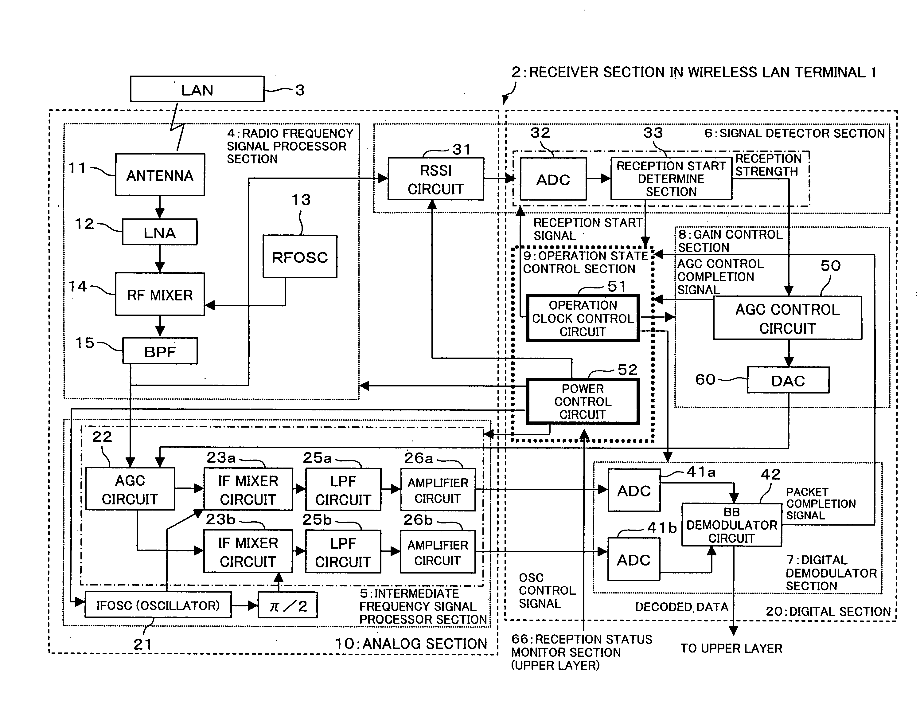
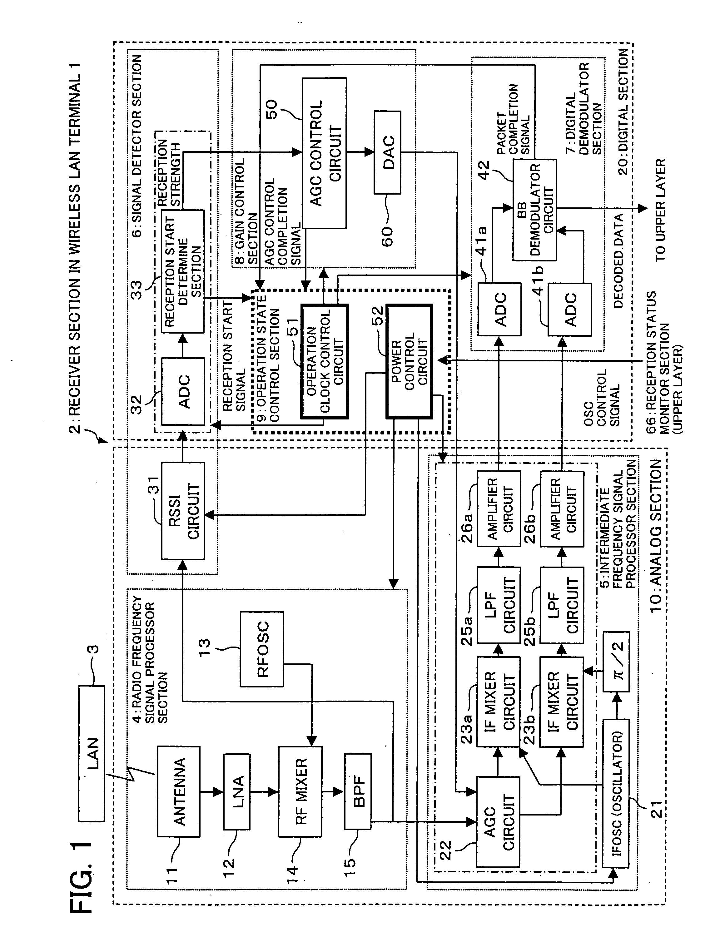
[0065] The following will describe an embodiment of the wireless LAN terminal (receiver device, communications device, wireless LAN device) of the present invention with reference to FIGS. 1, 2.

[0066] Referring first to FIG. 1, a receiver section 2 in a wireless LAN terminal 1 in accordance with the present embodiment has a double heterodyne structure composed chiefly of a radio frequency signal processor section 4, a signal detector section 6, an intermediate frequency signal processor section 5, a digital demodulator section (demodulator section) 7, a gain control section 8, and an operation state control section 9.

[0067] The radio frequency signal processor section 4, the intermediate frequency signal processor section 5, and a part of the signal detector section 6 (RSSI circuit 31) make up an analog section 10. Another part of the signal detector section 6 (ADC 32, reception start determine section 33), the digital demodulator section 7, the gain control section 8, and the ope...


PUM


Abstract

A receiver device in accordance with the present invention (for example, wireless LAN device) includes: a radio frequency signal processor section converting an incoming radio frequency signal to a lower frequency; an RSSI circuit (reception strength sensor section) sensing the signal strength of the radio frequency signal; an intermediate frequency signal processor section converting a signal from the radio frequency signal processor section to an even lower frequency; a digital demodulator section (demodulator section) demodulating a signal from the intermediate frequency signal processor section; and a power control circuit controlling power supply to circuits in the intermediate frequency signal processor section which makes up part of the analog section (AGC circuit, IF mixer circuit, LPF circuit, and amplifier circuit) according to a result of sensing by the RSSI circuit. The structure provides a power saving receiver device.

Description

[0001] This Nonprovisional application claims priority under 35 U.S.C. § 119(a) on Patent Application No. 2004-198605 filed in Japan on Jul. 5, 2004 and Provisional Patent Application No. 60 / 587,514 filed in the U.S., the entire contents of which are hereby incorporated by reference.FIELD OF THE INVENTION [0002] The present invention relates to power savings in receiver devices for, among others, double heterodyne or direct conversion wireless LAN terminals. BACKGROUND OF THE INVENTION [0003]FIG. 6 is a block diagram showing a conventional power saving structure for the wireless LAN device disclosed in Japanese unexamined patent application 8-307428 (Tokukaihei 8-307428 / 1996; published on 22 Nov. 1996). A receiver section 202 in the conventional wireless LAN device 201 includes: a radio section 225 which makes up the analog section; and a reception strength determine section 226, a power / clock control section 227, an A / D converter section 228, a despreader / demodulator section 229, a...

Claims


Application Information

Patent Timeline
Patent Type & Authority Applications(United States)
IPC IPC(8): H04L27/08
CPCH03G3/3052Y02D30/70
Inventor SHIRAKAWA, ATSUSHIUENO, TETSUOKITAYAMA, TAKAMITSU
Owner SHARP KK
Why Eureka
Try Eureka